Electric Power Steering System
8-4
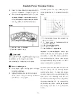
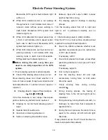
On the housing of ECU unit, there are sets of
electric plugs which function as follows:
• P1
:
positive pole (
○
+ pole) for EPS motor
• P2
:
negative pole (
○
- pole) for EPS motor
• P3
:
connected with a cable and transfers
signals to the ECU
• P4
:
connected with the steering torque
sensor, and supplies power to steering
torque sensor and accepts signals for
torque
• P5
:
connected with motor
4. Reducer
:
The reducer is installed on the frame of UTV.
A motor and steering torque sensor is also
installed on the reducer.
Outside view of reducer
5. Gear/rack type steering gear
UTV use gear/rack type steering gear to perform
steering function. Steering gear was fixed on
frame.
Installation position of steering as follows:
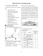
6. Electronic connectivity diagram of EPS
system
:
①
ECU (with waterproof metal box)
②
ECU split cable
③
Battery
④
Meter
⑤
Steering torque sensor
⑥
Motor
⑦
Speed sensor
⑧
Main switch
⑨
Fuse
Содержание SECTOR 1000
Страница 6: ...General 2 1 LOCATION OF PARTS Instrument Panel and Controls...
Страница 7: ...General 2 2 LOCATION OF PARTS...
Страница 8: ...General 2 3 ILLUSTRATED CONTENTS...
Страница 12: ...General 2 7 Warning and caution labels 1 2 3 4 5 6 7 8 9...
Страница 13: ...General 2 8 10 11 12 13 14...
Страница 74: ......
Страница 75: ...TM HISUN MOTORS 310 East University Dr McKinney Texas 75069 PH 972 446 0760 TF 877 838 6188 hisunmotors com...


