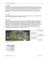
Slewing Sensing
© Hirschmann Rev. I 05/22/17
190154_I.DOC
13
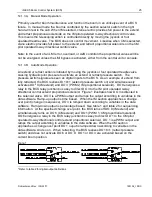
Modular Slew Pot - Output Currents
0
4
8
12
16
20
24
0
90
180
270
360
Degrees
mA
mA 2
mA 3
The converter board is supplied with 12V from the central unit. The potentiometer and the board
output two signals between 4 and 20mA that go to the central unit. You can measure them at the 12-
pin crane interface connector.
8.1
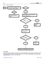
SLEW SENSING ERROR - FLOW CHART
(When the crane is over front, you should
see about 4mA in one channel (wire #2) and
12mA in the other channel (wire #3)).
Slew Sensing Error
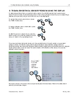
First, verify the slew angle displayed through
the console by using the sensor output screen.
Press the info
button twice
Slew potentiometer is
functioning correctly.
Does the
displayed value
differ from the
actual value?
The slew unit output can be found on pins 8 and 9. In order to
measure current, however, you must disconnect a pin and
measure in line (between the cable from the slew unit and the
central unit). *The two outputs will vary as shown in chart below.
NO
YES
Ensure that the slew pot unit
is supplied with crane voltage.
Pin 7 must carry crane
voltage and Pin 2 is GND.
You can also leave the wires connected as use your meter in
Voltage-mode to measure the output signals. In this case, you
will see the 4…20mA range as a 1.1 to 5.5 Volt range.
If the voltage or currents do not fall in line with the
charts and tables shown below, and no system errors
are present, the problem may be mechanical.
Open the slip ring unit and determine if the slew potentiometer is set correctly.


