3
State of delivery: switch in position 0 (Off),
i.e. SQE test function not active.
– you can switch on or off the SQE test fun-
ction at port 2 with the
SQE-Test Port 2
switch.
State of delivery: switch in position 0
(Off), i.e. SQE test function not active.
– you can switch on or off the monitoring
of the DTE voltage, for both ports
together, with the
DTEPower-Monitor
switch.
– ON: monitoring of the DTE voltage
active, data transmission only possible
if DTE voltage available.
– OFF: no monitoring of the DTE voltage,
data transmission always possible.
– State of delivery: switch in position 0
(OFF), i.e. no monitoring of DTE
voltage.
3. Assembly, startup procedure
and dismantling
3.1 UNPACKING, CHECKING
䡺
Check whether the package was deliver-
ed completely (see scope of delivery).
䡺
Check the individual parts for transport
damage.
z
Warning!
Use only undamaged parts!
3.2 ASSEMBLING MEDIA MODULES
Media modules can be assembled and
disassembled during running operation.
䡺
To fasten a media module, first remove
the protective cap over the plug of the
MICE.
䡺
Plug the media module onto the plug.
䡺
Tighten the 4 screws on the corners of
the media module.
䡺
Check whether the switch pre-setting
suits your requirements.
䡺
Fit the signal lines.
3.3 ASSEMBLING SFP MODULES
䡺
To fasten a SFP module, first remove
the protective cap over the socket.
䡺
Insert the SFP module with the closed
lock into the socket until you hear it
snap in.
Note:
Use only Hirschmann SFP modules.
3.4 ASSEMBLING THE MB-2T
EXPANSION MODULE
The MB-2T expansion module can be
installed while in running operation.
䡺
On the right side of the switch basic
module, loosen the screw at the top and
at the bottom (1-3 revolutions).
䡺
Remove the side cover.
䡺
If you have not yet done so, mount the
switch basic module onto the top-hat
rail.
䡺
Slide the MB-2T expansion module on
the top-hat rail toward the switch basic
module until the modules plug into
each other.
䡺
On the switch basic module, tighten the
screws at the top and at the bottom.
3.5 STARTUP PROCEDURE
You start up the MICE by connecting the
supply voltage via the terminal block(s) on
the MICE basic module. Lock the terminal
block(s).
3.6 CONNECTING THE
MM22-T1T1T1T1 POE MEDIA MODULE
The MM22-T1T1T1T1 PoE media module is
supplied with the PoE voltage (48 V DC
safety extra-low voltage) via an external
power supply unit. The PoE voltage is fed
into the 3-pin terminal block of the PoE
media module. The twisted pair cables are
supplied with the PoE voltage on port 1 to 4
via the spare pairs (pins 4&5 and 7&8 of the
RJ45 sockets).
Note:
Only use the Hirschmann
RPS60/48V EEC power supply unit for provi-
ding the PoE voltage.
䡺
Make sure that the external power
supply unit being used for providing the
PoE voltage meets, among other things,
the following requirements:
– Isolation requirements in compliance
with IEEE 802.3af (electrical strength
of the 48V output to “rest of the
world" 2250 V DC for 1 min.)
– Output power < 100 W.
– Current limiting < 2 A.
– Power supply unit and PoE media
module form a "Limited Power Sour-
ce" in compliance with IEC60950-1.
– The external PoE power supply unit
has to be able to provide the power
for the PDs being connected.
All these conditions are met by the
RPS60/48V EEC power supply unit.
䡺
Connect the PoE voltage to the 3-pin
terminal block (included in the scope of
delivery), as shown in the following
figure.
Make sure that your installation com-
plies with the following conditions:
– Length of the supply line < 3 m.
– Cross-section of the supply lines is
dimensioned for 1.5 A
Fig. 1: 3-pin terminal block of the
PoE media module
䡺
Mount the terminal block for the PoE
supply voltage on the bottom side of
the PoE module via snap lock. Push it
until it locks into position.
Note:
Use 4-pair twisted pair cables for
connecting the data terminal equipments.
Only connect data terminal equipments
which are conform to IEEE 802.3af.
4. Further support
In the event of technical queries, please talk
to the Hirschmann contract partner respon-
sible for looking after your account or
directly to the Hirschmann office. You can
find the addresses of our contract partners
– on the Internet
(http://www.hirschmann-ac.de)
Our support line is also at your disposal:
Tel. +49(1805) 14-1538
Fax +49(7127) 14-1551
Answers to Frequently Asked Questions can
be found on the Hirschmann product inter-
net sites on
www.hirschmann-ac.de
The FAQs are located under „Service“ in
the Automation and Control section.
www.hicomcenter.com
gives you an up-to-date overview of
training courses about technology and
products.
48 V
+
-
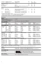
5. Technical data
Dimensions W x H x D
38 mm x 110 mm x 79 mm (MM2-...)
38 mm x 110 mm x 119 mm (MM3-..., MM4-...)
38 mm x 110 mm x 79 or 119 mm (MM20-..., MM21-..., MM22-..., MM30-...)
Humidity
10% to 95% (non condensing)
Atmospheric pressure
up to 2000 m (795 hPa, higher altitudes on demand)
Pollution degree
2
Laser protection
Class 1 conforming to EN 60825
Class 2M conforming to EN 60825-1:2003-10 (POF media modules ...-P4-...)
Protection type
IP 20
EMV interference proof
A
1)
B
1)
H
1)
EN 61000-4-2, Discharge of static electricity
Contact discharge: test level 3
4 kV
8 kV
8 KV
Air discharge: test level 3
8 kV
15 kV
15 kV
EN 61000-4-3, Electromagnetic fields
Test level 3 (80 - 2000 MHz)
10 V/m
20 V/m
20 V/m
EN 61000-4-4, Fast transients (burst),
- Power line
2 kV
4 kV
4 kV
Test level 3, x
- Data line
1 kV
4 kV
4 kV
EN 61000-4-5 Surge voltage
- Power line, line/line: test level 2
0,5 kV
1 kV
1 kV
- Power line, line/earth: test level 3
1 kV
2 kV
2 kV
- Data line: test level 3
1 kV
4 kV
4 kV


