Installation GREYHOUND Switch
Release 01 04/2016
Technical support
https://hirschmann-support.belden.eu.com
User Manual
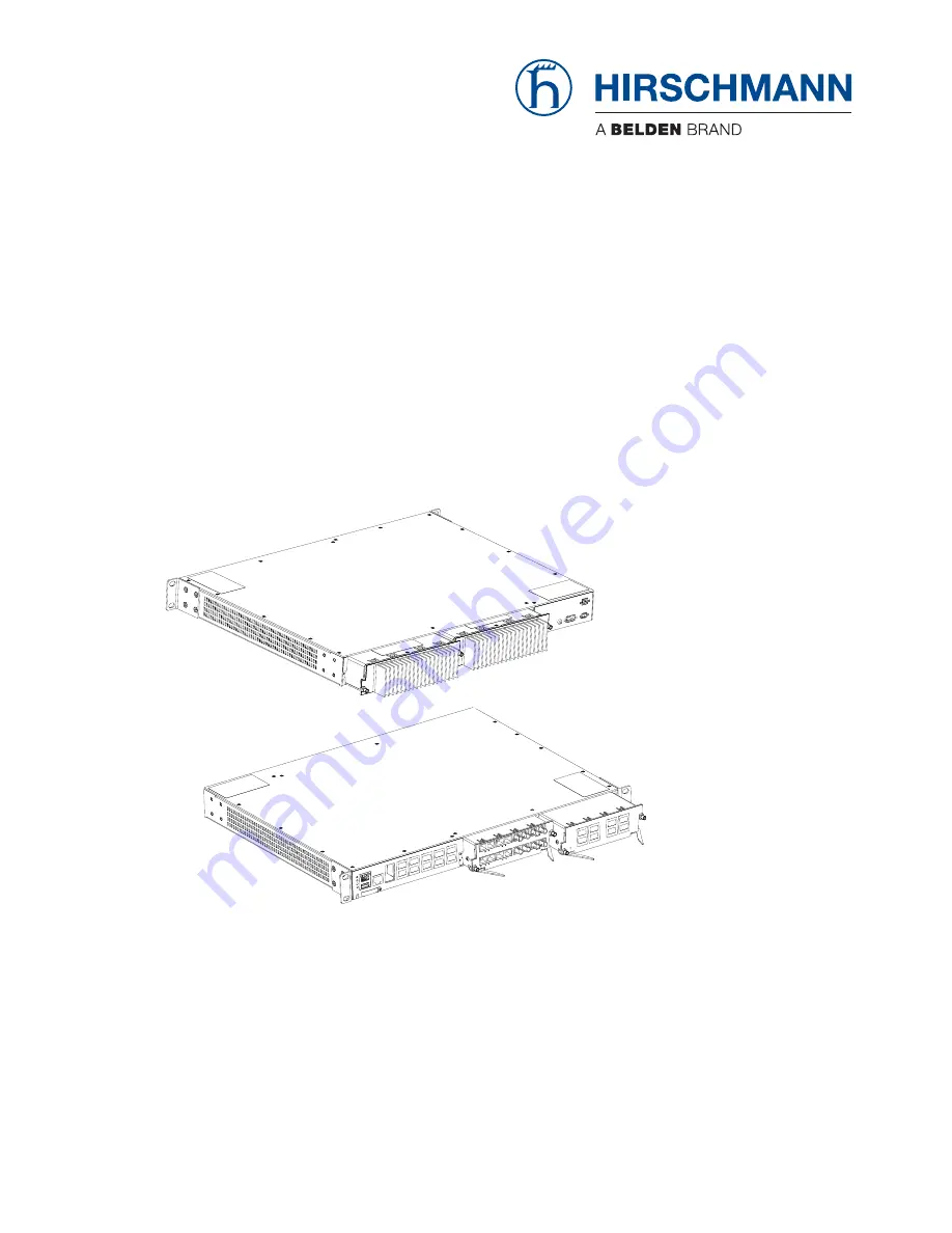
Installation
GREYHOUND Switch - GRS1042/GRS1142
GREYHOUND Power Supply Unit - GPS1/GPS2/GPS3
GREYHOUND Media Module - GMM20/30/32/40/42


