


3. Assembly and installation procedure HIRO 160 Q
20
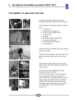
3.6 Installation of upper/lower lift stops
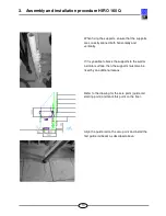
The
positive/negative
charging pins and the
emergency limit switch can be seen in the picture.
The accessories kit supplied contains the following
parts:
1. Charger unit
2. Wall mount for charger unit
3. Cable for the charging stations
4. Charging bars
5. Magnets
6. Radio transmitter and wall mount
7. Emergency end buffers
8. Bolts and screws and plug kit
9. Circuit diagram
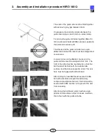
Install the charger unit with the wall mount near the
guide rails (lift stop).
The plates for the magnets and charging bar at the
lift stops have been factory-fitted in the lift stop
area.
The emergency contact strip and the limit stops
(buffers) have been factory-fitted at the upper and
lower lift stops.
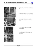
At the lower stop, the charging bars and the
magnets still have to be fitted.
Fit the long magnet approx. 120 mm before the
(round) magnet that is located at the lift stop.
After the learning run has been carried out, the lift
always stops at the centre of the round magnet.
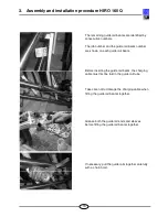
Position the charging bars (
positive
pole at the
top/
negative
pole at the bottom) at the "centre of
the charging pins" and connect them to the
charger unit.


