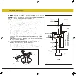
Hinkley SAWYER 36 Скачать руководство пользователя страница 6

UNPACKING YOUR FAN

UNPACK YOUR FAN AND CHECK THE CONTENTS.
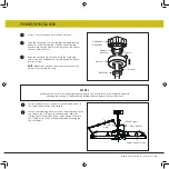
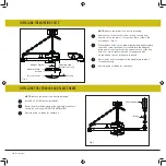
NOTE:

 Design of parts shown above may look slightly different for 

your specific model of fan.

04

|

hinkley.com

7-1

7-2

9

10

8

11

15

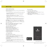
• Do not discard the carton. If warranty replacement or repair is ever necessary, the fan should be returned in original packing. Remove all 

parts and hardware. Do not lay motor housing on its side, or the decorative housing may shift, be bent or damaged.

• Examine all parts. You should have the following:

5-2

5-1

1

 PACKAGE CONTENT

1

2

Hanging Bracket

3

Ceiling Canopy and Trim Ring

C-Ring, Allen wrench

4

5-1

5-2

12” downrod assembly

24” downrod 

Yoke Cover

2

12

13

6

6-1

4

3

CA9000752Fxx

YC902928Fxx

DR94012Fxx

CR902928Fxx

990024Fxx

6

Fan Housing with Motor

Blade Set of 5

XX=FAN FINISH

x

7-1

6-1

7-2

8

9

10

11

12

13

15

12” chain Set w/couplers

24” chain Set w/couplers

Adapter Plate

Glass Shades

Bottom Cover

Hardware Bag

Bracket Mounting Hardware(wood 

screws, screws, lock washers, star 

washers, flat washers, wire nuts), 

Rubber Gasket, 

Balance Kit,

Safety cable hardware(wood screw, 

flat washer)

Receiver Incl. 5 Wire Nuts

4W LED Bulbs 

CH902912Fxx

BL902928Fxx

CH902924Fxx

GL902928SDY

LW902928Fxx

CNW902928

E901256LED LMP

MH902928Fxx


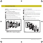
Cradle A, Wall Plate, Face Plate,
2 Mounting Screws,

Wall Control w/2032 Battery,

Cradle B (for flat wall use only)

+

980014FWH-R

Содержание SAWYER 36

Страница 1: ...36 SAWYER CEILING FAN INSTRUCTION MANUAL INDOOR OUTDOOR LED FAN LED WET WIFI DC DC MOTOR ...

Страница 2: ... installation and operation of this fan It has been designed to make the installation process as easy as possible If you are unfamiliar or uncomfortable with wiring please contact a qualified electrician If you need additional assistance or have any questions please reach out to us For warranty information visit hinkley com SERVICE HINKLEY COM 800 HINKLEY LET S SEE THAT HINKLEY STYLE HINKLEY HINKL...

Страница 3: ...MPORTANT SAFETY PRECAUTIONS 03 TOOLS MATERIALS REQUIRED 04 UNPACKING YOUR FAN 05 PREPARATION 05 INSTALLING THE HANGING BRACKET 06 HANGING THE FAN 08 ELECTRICAL CONNECTIONS FINISHING THE INSTALLATION 09 INSTALLING THE MONTING PLATE 10 10 11 INSTALLING THE LED BULBS AND GLASS SHADES 13 INSTALLING THE WALL CONTROL 15 15 16 OPERATION CARE AND CLEANING TROUBLESHOOTING 16 17 ENERGY GUIDE SPECIFICATIONS ...

Страница 4: ...e carton until ready to be installed to protect its finish If you are installing more than one ceiling fan make sure that you do not mix fan blade sets as each blade is part of a weighted set After making electrical connections spliced conductors should be turned upward and pushed carefully up into outlet box The wires should be spread apart with the common conductor and the grounding conductor on ...

Страница 5: ...03 Disconnect power by removing fuse or turning off circuit breaker before installing the fan and or optional lighting Support directly from building structure To reduce the risk of fire electric shock or personal injury mount to outlet box marked acceptable for fan support and use mounting screws provided with the outlet box Most outlet boxes commonly used for the support of lighting fixtures are no...

Страница 6: ...C Ring Allen wrench 4 5 1 5 2 12 downrod assembly 24 downrod Yoke Cover 2 12 13 6 6 1 4 3 CA9000752Fxx YC902928Fxx DR94012Fxx CR902928Fxx 990024Fxx 6 Fan Housing with Motor Blade Set of 5 XX FAN FINISH x 7 1 6 1 7 2 8 9 10 11 12 13 15 12 chain Set w couplers 24 chain Set w couplers Adapter Plate Glass Shades Bottom Cover Hardware Bag Bracket Mounting Hardware wood screws screws lock washers star w...

Страница 7: ...ce with National and Local Electrical Codes and the ceiling fan must be grounded as a precaution against possible electric shock 1 2 3 4 Locate ceiling joist where fan is to be mounted being sure location agrees with the requirements in the minimum clearance section of this guide Wood joists must be sound and of adequate size to support 35 pounds See page 2 items 3 and 4 If not already present mou...

Страница 8: ...es come out facing upward Loosen the two security set screws and remove the downrod pin and retaining clip from the coupling on top of the motor assembly Fig 2 Carefully feed the electrical lead wires and safety cable from the fan through the downrod Thread downrod into coupler until holes align Insert downrod pin through holes in mounting collar and downrod clip cotter pin through small hole in e...

Страница 9: ...ons Slide canopy up and fasten to hanger bracket with 4 screws provided Fig 3 Ground Wire Hook up 3 Wires Downrod Cross Pin Hanger Ball Set Screw Top of Fan Body Yoke Cover Canopy Trim Ring C Ring Safety Cable Fig 4 Attach the wood screw and the flat washer to the ceiling joist as shown do not fully tighten Slide the cable clamp onto the safety cable from the fan Loop the safety cable around the wo...

Страница 10: ... to the YELLOW receiver wire Connect the GRAY fan wire to the GRAY receiver wire Connect the RED fan neutral wire to the RED receiver neutral wire Connect the WHITE neutral light kit lead from the fan to WHITE receiver lead marked For Light Connect the BLACK light kit lead from the fan to BLUE receiver lead marked For Light Wire colors out of the fan are black white for the light kit Light kit lea...

Страница 11: ...til the canopy and trim ring are snug Loosen the buckles at one end of the chain and attach to the chain support loops of the fixture Loosen the remaining buckles of the chain ends and install the chain to the C Ring on the fan downrod Slide the C Ring up the downrod until the chains are taunt Secure the C Ring into position on the downrod by securing the two set screws WARNING Make sure the hook ...

Страница 12: ...the key holes Secure by tightening the 2 screws previously loosened and the one previously removed Raise the bottom cover against the adapter plate with 2 screws until snug Restore power is ready for operation Fig 2 Screws Screws Mounting Hub bottom of motor Adapter Plate Bottom Cover Rubber Gasket 4 INSTALLING THE LED BULBS AND GLASS SHADES 1 2 3 Fig 3 NOTE Be sure the power is off before installi...

Страница 13: ... bracket Remote transmitter will be held in place with built in magnets Remove the existing wall plate and the old switch from the wall outlet box Seat the cradle A into the wall plate Fig 2 Connect the black lead wires from the switch in the cradle A to the black wires in the switch box Hot input wire to one of the cradle A switch leads Power lead to the fan is connected to the remaining switch l...

Страница 14: ...emaining switch lead Fig 4 Attach the cradle A to the wall switch box using the supplied hardware Attach the multi gang faceplate to the switch set in the wall outlet box Cradle A of Hinkley switch will fit in any standard decora face plate Remote transmitter will be held in place with built in magnets 1 2 3 4 5 Option 3 Multi Gang Wall Switch Box Installation Fig 4 Outlet box Face plate Switch Ou...

Страница 15: ...ody it can cause severe internal burns and can lead to death in as little as 2 hours Always completely secure the battery compartment If the battery compartment does not close securely stop using the product remove the batteries and keep it away from children IF you think batteries might have been swallowed or placed inside any part of the body seek immediate medical attention The batteries shall ...

Страница 16: ...sing Slide the switch to the right for winter mode operation Slide the switch to the left for summer mode operation Make sure switch is not stuck between forward and reverse positions Summer Mode forward A DOWNWARD airflow creates a cooling effect as shown in Figure 3 This allows you to set your air conditioner on a warmer setting without affecting your comfort Winter Mode Reverse An UPWARD airflow mo...

Страница 17: ... the canopy is firmly attached to hanging bracket and not vibrating against ceiling 1 Check that all blades are firmly screwed into blade arms Check that all blade arms are firmly secure to the motor 2 Check to make sure that light kit if present is firmly attached to switch housing and that all glassware and shades are fastened properly Wobble can also result from even the smallest deviations in dist...

Страница 18: ...se per day Your cost depends on rates Energy Use 8 Watts and use 3 34 Cost Range of Similar Models 19 84 2 Estimated Yearly Energy Cost All estimates based on typical use excluding lights Airflow Shown Is a Weighted Average of High and Low Cubic Feet per Minute Based on Downrod 2432 735 10 7 2 1 228 352 PERFORMANCE SPECIFICATIONS STANDARD HIGH SPEED LOW SPEED Airflow CFM Energy Use Watts Airflow Effic...

Страница 19: ...eset Method a Turn mains power OFF to the fan b Turn mains power back ON on the fan c Hold down the Power button on the transmitter for 5 seconds until the fan light flashes 3 times d Repeat steps a c above 4 more times e The fan s memory is now totally overwritten and it has forgotten all other remotes Brute Force Method https bondhome io app HINKLEY SMART FAN OPTIONS In addition to the included w...

Страница 20: ...UCTS THAT ENHANCE YOUR SPACE WITH COMFORT PURPOSE AND STYLE AS A FAMILY COMPANY WE ARE COMMITTED TO DESIGN PERFORMANCE AND QUALITY AND WHAT S IMPORTANT TO YOU IS PARAMOUNT TO US FOR A COMPLETE ASSORTMENT OF OUR PRODUCTS AND SOURCE BOOKS VISIT HINKLEY COM ...

Страница 21: ...GLOBAL HEADQUARTERS 33000 Pin Oak Parkway Avon Lake Ohio 44012 T 440 653 5500 F 440 653 5555 hinkley com ...

Отзывы: