background image

Lifecycle 

System 

Page 98 of 110 

HI 803 211 E Rev. 1.01.00 

9.1.5 

Grounding and Shielding Concept of HIMA Control Cabinets 

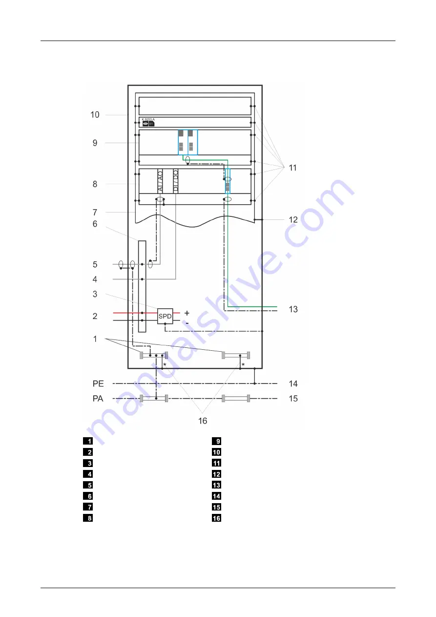
The following figure shows the grounding and shielding concept of a HIMA control cabinet: 


  M 2500 busbar 

  24 VDC supply 

  Filter (surge protective device) 

  Digital signals 

  Analog signals 

  Inline terminals 

  Pivoting or fixed frame 

  Extension rack 

  Base rack 

  Cabinet frame 

  Cage nuts and cage clamps 

  25 mm grounding connector 

  Shielded bus cable 

  Protective ground 

  Equipotential bonding 

  Standard connection to HIMA control cabinets, to 

delete if equipotential bonding is applied. 

Figure 35:  Grounding and Shielding Concept of the HIMA Standard Cabinet 


Содержание HIQuad H41X

Страница 1: ...Manual HIQuad X System Manual...

Страница 2: ...uestions please contact HIMA directly HIMA appreciates any suggestion on which information should be included in the manual Equipment subject to change without notice HIMA also reserves the right to m...

Страница 3: ...3 2 Concept for HIQuad H51X 14 3 2 1 The H51X Mono System 15 3 2 2 The H51X Redundancy System 17 3 3 Concept for HIQuad H41X 20 3 3 1 The H41X Mono System 21 3 3 2 The H41X Redundancy System 23 3 4 E...

Страница 4: ...Watchdog WD 52 4 7 Modules 53 4 8 F CPU 01 Processor Module 53 4 8 1 Operating System 53 4 8 1 1 General Cycle Sequence 53 4 8 1 2 Operating System States 53 4 8 2 Behavior in the Event of Faults 56 4...

Страница 5: ...Configuration Version Parameter 76 6 1 3 6 Rack System Variables 77 6 1 3 7 Locking and Unlocking the Resource 81 6 2 Forcing 82 6 2 1 Time Limits 83 6 2 2 Restricting the Use of Forcing 83 6 2 3 For...

Страница 6: ...Systems 100 9 1 11 Cable Colors 100 9 1 12 Connecting the Supply Voltage 100 9 2 Start Up 101 9 2 1 Starting up the Control Cabinet 101 9 2 1 1 Test of All Inputs and Outputs 101 9 2 1 2 Voltage Conne...

Страница 7: ...ding manual Lifecycle Phases of a HIQuad X system lifecycle Installation Start up Maintenance and repairs HIQuad X Documentation Overview of the documentation Appendix Glossary Index of tables and ind...

Страница 8: ...nk to jump to the corresponding position Safety notices and operating tips are specially marked 1 3 1 Safety Notices Safety notices must be strictly observed to ensure the lowest possible risk The saf...

Страница 9: ...0 Page 9 of 110 1 3 2 Operating Tips Additional information is structured as presented in the following example i The text giving additional information is located here Useful tips and tricks appear a...

Страница 10: ...tive Maintenance HIMA is responsible for planning and executing preventive maintenance measures Maintenance actions are carried out in accordance with the manufacturer s specifications and are documen...

Страница 11: ...Accordance with the Energize to Trip Principle The HIQuad X system can also be used in applications that operate in accordance with the energize to trip principle A system operating in accordance with...

Страница 12: ...ctrostatic discharge e g by storing them in their packaging 2 3 Residual Risk No imminent risk results from a HIMA system itself Residual risk may result from Faults related to engineering Faults in t...

Страница 13: ...apter 4 9 The I O processing module F IOP 01 uses the I O bus to interconnect the I O modules within one rack The F IOP 01 module safely communicates with the processor modules via one or two system b...

Страница 14: ...oint connection The processor module in slot 8 controls and monitors system bus A whereas the processor module in slot 10 controls and monitors system bus B During redundant operation the two processo...

Страница 15: ...s results are sent to the I O processing module which writes them to the output modules The output modules thus control the field level e g the actuators During mono operation the signal is forwarded...

Страница 16: ...ase rack Figure 3 Example of H51X Mono System The rack IDs do not necessarily have to be arranged as described above but they must be unique To ensure a clearer overview HIMA recommends the following...

Страница 17: ...while the system is operating Figure 4 Example of Safe H51X Redundant Operation 1oo2 In contrast to mono operation the entire design of a redundant system is intended to ensure availability Redundant...

Страница 18: ...racks can be connected to the system buses in a UP loop DOWN loop or UP and DOWN loop The extension racks are interconnected with system buses A and B via the I O processing module see F IOP 01 manua...

Страница 19: ...ck IDs do not necessarily have to be arranged as described above but they must be unique To ensure a clearer overview HIMA recommends the following Arrange the rack IDs in accordance with Figure 5 Bet...

Страница 20: ...operation the two processor modules align their data The RJ 45 system bus interfaces on the rear side of the base rack are used to connect the I O modules in the H41X base rack to the processor module...

Страница 21: ...ser program s results are sent to the I O processing module which writes them to the output modules The output modules thus control the field level e g the actuators During mono operation the signal i...

Страница 22: ...System bus interfaces on the rear side of the base rack Figure 8 Example of H41X Mono System The rack IDs for the HIQuad H41X system are fixed To ensure a clearer overview HIMA recommends the followin...

Страница 23: ...n contrast to mono operation the entire design of a redundant system is intended to ensure availability Redundant input modules safely record the values measured by redundant sensors They exchange dat...

Страница 24: ...if one system bus is disconnected the system can continue to operate via the redundant system bus If one I O processing module fails the I O modules in the affected rack enter the safe state while th...

Страница 25: ...of 16 I O modules to be inserted in slots 1 16 The I O processing module is used to connect the system buses to the I O bus The power distribution modules F 7133 are used to fuse and distribute L and...

Страница 26: ...at dissipation of a HIMA standard cabinet achieved by convection i e without additional aids is 300 W This assumes installation of several cabinets next to each other and with their rear side to the w...

Страница 27: ...net Total power dissipation Maximum power dissipation per extension rack Fan components 300 W 50 W 3 x K 9203A 300 500 W 50 W 3 x K 9203A K 9202B 500 1000 W 100 W 3 x K 9203A K 9202B Table 3 Fan Compo...

Страница 28: ...4 x W x H D 1 8 x H x D Final enclosure free standing A 1 4 x D x W H 1 8 x W x H Final enclosure for wall mounting A 1 4 x H x W D 1 4 x W x D Central enclosure free standing A 1 8 x W H 1 4 x W x D...

Страница 29: ...rack H51X Backplane H41X Backplane Extension rack backplane Table 6 Rack Backplanes 4 2 19 Inch Frame The 19 inch frame is the basic mechanical structure of the HIQuad X system The following figure sh...

Страница 30: ...figure shows the dimensions of the 19 inch frame a External dimensions 482 6 mm b Mounting space 84 HP 84 x 5 08 mm c Mounting hole distance 465 mm d Mounting depth 263 mm c Mounting hole distance 101...

Страница 31: ...02 XG6 Figure 15 Rear View of H51X Backplane 4 2 1 1 Supply of the H51X Base Rack For supply and power distribution HIMA recommends using the following components K 7205 Redundant supply up to a maxim...

Страница 32: ...Power Supply for Extension Racks The 5 V power supply for extension racks is connected to the following terminals Spring terminal Cross section and color XG2 1 XG2 13 Vcc 2 5 mm YE XG3 1 XG3 13 Vcc 2...

Страница 33: ...12 slot 1 slot 12 XG3 LS slot 1 slot 12 XG4 LS reference potential for auxiliary voltage 24 VDC XG8 Figure 16 Rear View of H41X Backplane 4 2 2 1 Supply of the H41X Base Rack For supply and power dist...

Страница 34: ...use XG9 1 2 L1 L2 2 5 mm RD Maximum 16 A gL XG 10 1 2 L 2 5 mm BK Table 11 Connection to the 24 V Power Supply 4 2 2 2 5 V Power Supply for Extension Racks The 5 V power supply for the extension rack...

Страница 35: ...V Auxiliary Voltages in I O Modules The connection to the 24 V power supply of the cable plugs is performed as shown in Figure 17 The Faston flat connectors XG3 and XG4 are supplied via field termina...

Страница 36: ...free use XG6 Do not use it for HIQuad X L 24 VDC XG 11 Do not use it for HIQuad X GND 5 VDC XG 12 Potential distributor for free use XG13 Potential distributor for free use XG14 Figure 18 Rear View of...

Страница 37: ...rature threshold Temperature state Temperature State X BYTE 40 C Normal 0x00 40 C Warning Threshold 1 exceeded 0x01 60 C Error Threshold 2 exceeded 0x03 Table 14 Thresholds of the Temperature States I...

Страница 38: ...r supply units see Figure 19 Redundant with redundant power supply units see Figure 20 HIMA uses red cables for positive potentials L and black cables for negative potentials L Decoupled SELV PELV pow...

Страница 39: ...HIMA power supply units of the PS 1000 series are designed and suitable for a mean time to failure MTTF of 30 years Power supply units from other manufacturers must be checked to ensure that they mee...

Страница 40: ...aximum current input in each base rack to 16 A Users must implement external measures to ensure that the power supply does not fall below 0 8 x UN 19 2 VDC If no redundant power supply is available th...

Страница 41: ...e 19 Connection to one or redundant power supply units see Figure 19 Connection to 24 VDC for the I O processing modules from the same source as the H51X base rack Redundant supply of the F 7133 power...

Страница 42: ...ower supply units and for the I O level at the connection for mono components see Figure 20 Connection to redundant power supply units see Figure 20 Attach to the connector for mono components see Fig...

Страница 43: ...the extension racks with odd rack IDs while a redundant power supply unit L2 powers the racks with even IDs In this example the redundancy of the I O level is portioned based on the rack IDs so that...

Страница 44: ...The buffer module in slot 7 compensates for voltage dropouts of the expansion racks with even rack IDs In doing so redundant I O levels can be assembled based on the rack IDs If one buffer module fail...

Страница 45: ...ee Figure 19 Inline terminals XG5 1 XG5 13 to 24 V power supply XG5 13 for connecting to the I O processing modules Connection to one or redundant power supply units see Figure 19 Connection to 24 VDC...

Страница 46: ...g module in the extension rack terminals XG 3 L see Figure 20 The power supply units must be able to bridge voltage dropouts of up to 20 ms Inline terminals XG5 1 XG5 13 to 24 V power supply XG5 13 fo...

Страница 47: ...O modules is as follows F 7133 power distribution module Supplies the I O modules in Slot 18 Slot 1 4 Slot 19 Slot 5 8 Slot 20 Slot 9 12 Slot 21 Slot 13 16 Table 15 Assignment of F 7133 Power Distrib...

Страница 48: ...d XG5 for GND The supply voltage is distributed in a star configuration see Figure 25 The resistance of a 5 V supply line with a maximum length between H51X base rack and extension rack of 12 m must b...

Страница 49: ...oduct Description HI 803 211 E Rev 1 01 00 Page 49 of 110 GND connectors XG4 and XG5 on the rack rear side 5 VDC connectors XG2 and XG3 on the rack rear side Figure 28 Extension Rack Connected to a 5...

Страница 50: ...stem is distributed among two control cabinets the 5 V power supply must be provided in the control cabinet without base rack by a separate power supply unit see Chapter 4 3 8 for details The wires on...

Страница 51: ...ration communication runs on both system buses simultaneously If only one processor module is inserted in the base rack the system runs in mono operation with only one system bus Redundant operation e...

Страница 52: ...um System Bus Latency s is set to System Defaults the maximum system bus latency is determined by the system For the 100 s setting the maximum system bus latency is set to this value For system bus co...

Страница 53: ...s Controlling the cyclic run of the user programs Performing the self tests of the module Controlling safety related communication via safeethernet Managing the processor modules redundancy synchroniz...

Страница 54: ...No valid configuration is available in the memory Loading with error STOP LOADING OS Processor module stopped The operating system is loaded in the non volatile memory Loading the operating system us...

Страница 55: ...ATION Processor module stopped No valid configuration is available in the memory Loading with error STOP LOADING OS Processor module stopped The operating system is loaded in the non volatile memory L...

Страница 56: ...g a PADT command to stop STOP state Table 19 Operating System States User Interventions i The cycle time increases by the number of modules used in the system This applies irrespective of whether or n...

Страница 57: ...ng module The module s tasks include exchanging data with the processor modules and providing the watchdog signal to the output modules via system bus A and system bus B 4 10 F COM 01 Communication Mo...

Страница 58: ...5 Z 7035 3335 4 3 DO Ex i HI 803 187 E F 3349 Z 7150 3349 8 3 DO 0 5 A HI 803 188 E F 3422 Z 7139 3422 8 Relay 60 VDC HI 803 189 E F 3430 Z 7149 3430 4 3 Relay 110 VDC HI 803 190 E F 5220 Z 7152 5220...

Страница 59: ...t for up to one cycle before it is detected while reading in the values the minimum noise blanking time can be determined by subtracting a cycle from the maximum noise blanking time value Minimum nois...

Страница 60: ...on of the read in process If the interference is still present in the following cycle during the read in process the module detects the interference and the system decides if noise blanking can be per...

Страница 61: ...cides if noise blanking can be performed at this point in time based on the following rule Safety time elapsed time 2 x watchdog time 0 Noise blanking is possible in the 1st and 2nd cycle since the in...

Страница 62: ...es the transient interference on the input module and on the buses system bus and I O bus Noise blanking on the input module can be deactivated in the properties SILworX default Activated see the inpu...

Страница 63: ...opped Afterwards the user program cannot be started without a valid software activation code for the protocols used in the project invalid configuration 4 14 Connecting the PADT to the System The phys...

Страница 64: ...he corresponding page for more details To activate a function with an activation code 1 Generate the software activation code on the HIMA website www hima com en using the system ID of the controller...

Страница 65: ...y related operation is still ensured even if one of the two redundant processor modules fails 5 1 2 Increasing Redundancy If a new processor module is added to a running HIQuad X system it automatical...

Страница 66: ...assigned to a channel channel number to both channels of the redundant modules Refer to the Hardware Editor section of the SILworX online help for more details 5 3 System Bus Redundancy The HIQuad X s...

Страница 67: ...t affect the user program Local and global variables exist Local variables are valid in a delimited project area in a user program or function block Global variables can be used in several function bl...

Страница 68: ...permissible variable types in connection with the structure tree nodes Type Project Configuration Resource Program type Function block type Function type VAR X VAR_EXTERNAL X VAR_GLOBAL X X X 1 VAR_I...

Страница 69: ...rameters are defined at different project levels The system variables and parameters are configured in SILworX either in the Properties dialog box of the corresponding structure tree node or in the de...

Страница 70: ...ycle time see Target Cycle Time Mode Range of values 0 7500 ms Default value 0 ms can be changed online The maximum target cycle time value may not exceed the configured Watchdog Time ms minus the min...

Страница 71: ...cense is required for setting the maximum system bus latency to a value System Defaults Application specific Allow Online Settings Y TRUE All the switches parameters listed under FALSE can be changed...

Страница 72: ...ult setting is TRUE Application specific FALSE Global forcing is not permitted for this resource Global Force Timeout Reaction N Specifies how the resource should behave when the global force timeout...

Страница 73: ...is the number of changed user programs The default setting is Fixed tolerant i After the first reload activation cycle the values of watchdog time target cycle time and target cycle time mode apply i...

Страница 74: ...the Max Com Time Slice ms system parameter located in the properties of the resource For each F COM module 3 ms For each redundant safeethernet connection 1 ms For each non redundant safeethernet con...

Страница 75: ...Config System parameter Max Duration of Configuration Connections ms nCOM Number of modules with Ethernet interfaces CPU COM nRIO Number of configured remote I Os nPADT Maximum number of PADT connecti...

Страница 76: ...compatible with the operating systems of the modules The value of Minimum Code Generation only needs to be increased for converted projects if additional functions of a controller should be used If fe...

Страница 77: ...cific 1 The operating system handles the system parameter in a safety related manner yes Y or no N Table 26 System Parameters for Output Variables Input Variables Variables that are not selected in th...

Страница 78: ...milliseconds and seconds since 1970 01 01 0 999 ms 0 4 294 967 295 s UDINT Last Communication Warning ms Last Communication Warning s N Date and time of the last communication warning in milliseconds...

Страница 79: ...L Read Only in RUN Y TRUE The following operator functions are locked Stop Start Download FALSE The following operator functions are unlocked Stop Start Download BOOL Redundancy Info Y Bit coded redun...

Страница 80: ...TE Remaining Global Force Duration ms Y Time in ms until the time limit set for global forcing expires DINT Watchdog Time ms Y Maximum permissible duration of a RUN cycle in ms dependent on the contro...

Страница 81: ...ibes a simple case in which a key operated switch is used to lock or unlock all interventions to the resource Example To make a controller lockable 1 Define a global variable of type BOOL and set its...

Страница 82: ...ible for the acceptance test Only remove existing forcing restrictions with the consent of the test authority responsible for the acceptance test When forcing values the person in charge must take fur...

Страница 83: ...tely using a key switch To do so the Force Deactivation system variable must be linked to a digital input connected to a key switch WARNING Failure of safety related operation possible due to forced v...

Страница 84: ...rogram and forcing 6 2 5 Forcing and Scalar Events When forcing a global variable used to create scalar events observe the following points The events are created in accordance with the force value Th...

Страница 85: ...ete change user accounts user groups and the user management and define the default user account They may also perform all SILworX functions Read and Write Allows users to perform SILworX functions ex...

Страница 86: ...operating voltage The user accounts of a controller also apply to the connected remote I Os Users log in to a controller using the user group name and password If they use the user group name belongin...

Страница 87: ...modules Reset cycle time and fault statistics Set the system time restart and reset the modules Start system operation for processor modules Forcing Read Write Similar to Read Operator but users may a...

Страница 88: ...oup Always define a password for the PES user account with Administrator access mode i Generally passwords are to be used Suitable passwords are composed of more than 10 characters and contain numbers...

Страница 89: ...s Blinking1 see the following tables The indication of errors or faults has priority over the indication of warnings Warnings cannot be reported if errors or faults are being signaled 7 2 Diagnostic H...

Страница 90: ...ype MMMM status Mod mm OUT AAAA IN EEEE channel OUT aaaa IN eeee The following table describes the data fields in the message Data field Format Description S Decimal Slot number of the I O module MMMM...

Страница 91: ...Module Type Text Permissible module types Type of module which is plugged into the rack Configured Module Type Text Permissible module types Type of module which is configured and loaded in the contro...

Страница 92: ...s A Value Description 0 The interface is OK 1 The interface detected an error during last reception now it is OK 2 An error occurred on the interface 3 The interface is switched off Connection Status...

Страница 93: ...ply Input Voltage 24 VDC 15 20 rp 5 SELV PELV Table 34 Environmental Conditions 8 2 Dimensioning For details refer to the component specific manuals and communication manual HI 801 101 E For each reso...

Страница 94: ...the conditions of use specified in Chapter 2 1 Observe the instructions for installing base racks and other components specified in the corresponding manuals 9 1 2 Connecting the Field Level The fiel...

Страница 95: ...ogether with field lines or 24 VDC supply lines For further information see Chapter 9 1 3 2 Observe the instructions provided in this manual related to grounding shielding and cable routing to sensors...

Страница 96: ...face of the pivoting frame 1 ensuring safe electrical contact Stainless steel screws and flat washers are used to prevent electrical corrosion 2 The components of the cabinet frame 3 are welded togeth...

Страница 97: ...mm2 grounding straps 5 The busbars can also be used as a separate potential e g to connect to the field cable shielding if the grounding straps between the busbars and the control cabinet are removed...

Страница 98: ...VDC supply Filter surge protective device Digital signals Analog signals Inline terminals Pivoting or fixed frame Extension rack Base rack Cabinet frame Cage nuts and cage clamps 25 mm grounding conne...

Страница 99: ...d faults occur faulty control signals can be triggered For this reason HIMA recommends using ground fault monitoring for ungrounded operation Some application standards e g DIN EN 50156 1 2005 prescri...

Страница 100: ...o avoid compensation currents Additionally the requirements specified in the module specific manuals must be observed 9 1 10 Lightning Protection for Data Lines in HIMA Communication Systems Lightning...

Страница 101: ...on of ground fault measuring facility which may be connected to the system A megohmmeter or a special measuring instrument must be used to check each connection against ground 9 2 1 2 Voltage Connecti...

Страница 102: ...t If the system is only equipped with one processor module mono system set mono operation To do so click Set Mono Redundancy Operation in the Online Start up menu This setting only takes effect if a m...

Страница 103: ...g to the power supply the HIQuad X system modules start in random order This applies to the HIQuad X modules as well as to the connected remote I Os 9 3 2 Connecting the Redundant Power Supply Because...

Страница 104: ...rst steps manual HI 801 103 E Introduction for engineering HIMA controllers using SILworX PDF SILworX online help CHM Communication manual HI 801 101 E Communication protocols and their application PD...

Страница 105: ...ty related module has no influence on the safety related modules MAC Address Media access control address hardware address of one network connection PADT Programming and debugging tool in accordance w...

Страница 106: ...H41X 35 Figure 18 Rear View of Extension Rack Backplane 36 Figure 19 Mono 24 V Power Supply 38 Figure 20 Redundant 24 V Power Supply 39 Figure 21 Mono Connection to H51X Base Rack 24 VDC 41 Figure 22...

Страница 107: ...Power Supply Units 51 Table 17 Allowed Power Consumption in Relation to the Number of Power Supply Units 51 Table 18 Operating System States States Entered 55 Table 19 Operating System States User In...

Страница 108: ...Diagnostic message I O module 89 Diagnostics 88 History 88 Energize to trip principle 11 ESD protection 12 Loading the operating system 102 PADT user management 84 PES user management 85 Programming 6...

Страница 109: ......

Страница 110: ...t notice 2017 by HIMA Paul Hildebrandt GmbH Specifications subject to change without notice MANUAL System HI 803 211 E For further information please contact HIMA Paul Hildebrandt GmbH Albert Basserma...

Отзывы: