


Digital Video Recorder User Manual
126
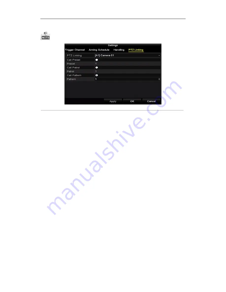
8.
Select
PTZ Linking
tab and set PTZ linkage of the POS alarm.
Set PTZ linking parameters and click the
OK
button to complete the settings of the alarm input.
Please check whether the PTZ or speed dome supports PTZ linkage.
Figure 9. 14
Set PTZ Linking
9.
Click
OK
to save the settings.
Содержание UD01394B
Страница 1: ...Digital Video Recorder User Manual UD01394B...
Страница 13: ...Digital Video Recorder User Manual 12 Chapter 1 Introduction...
Страница 29: ...Digital Video Recorder User Manual 28 Chapter 2 Getting Started...
Страница 46: ...Digital Video Recorder User Manual 45 Chapter 3 Live View...
Страница 55: ...Digital Video Recorder User Manual 54 Chapter 4 PTZ Controls...
Страница 65: ...Digital Video Recorder User Manual 64 Chapter 5 Recording Settings...
Страница 86: ...Digital Video Recorder User Manual 85 Chapter 6 Playback...
Страница 100: ...Digital Video Recorder User Manual 99 Chapter 7 Backup...
Страница 106: ...Digital Video Recorder User Manual 105 Chapter 8 Alarm Settings...
Страница 111: ...Digital Video Recorder User Manual 110 Figure 8 9 Copy Settings of Alarm Input...
Страница 120: ...Digital Video Recorder User Manual 119 Chapter 9 POS Configuration...
Страница 124: ...Digital Video Recorder User Manual 123 Figure 9 10 Copy POS Settings...
Страница 128: ...Digital Video Recorder User Manual 127 Chapter 10 VCAAlarm...
Страница 139: ...Digital Video Recorder User Manual 138 Chapter 11 VCA Search...
Страница 146: ...Digital Video Recorder User Manual 145 Chapter 12 Network Settings...
Страница 160: ...Digital Video Recorder User Manual 159 Figure 12 28 Packet Export Attention Up to 1M data can be exported each time...
Страница 163: ...Digital Video Recorder User Manual 162 Chapter 13 HDD Management...
Страница 176: ...Digital Video Recorder User Manual 175 Chapter 14 Camera Settings...
Страница 180: ...Digital Video Recorder User Manual 179 Chapter 15 DVR Management and Maintenance...
Страница 188: ...Digital Video Recorder User Manual 187 Chapter 16 Others...
Страница 197: ...Digital Video Recorder User Manual 196 Chapter 17 Appendix...
Страница 220: ...Digital Video Recorder User Manual 219...


