background image

Mobile Digital Video Recorder User Manual 

25 

2.5


Camera Settings 

Purpose:   

You can configure the camera name, OSD (On Screen Display) settings, etc. 


The  settings  of  OSD,  standing  for  On  Screen  Display,  include  the  display  of  camera  name,  date  and  week  and  the 

corresponding position information. 

Steps:


1.


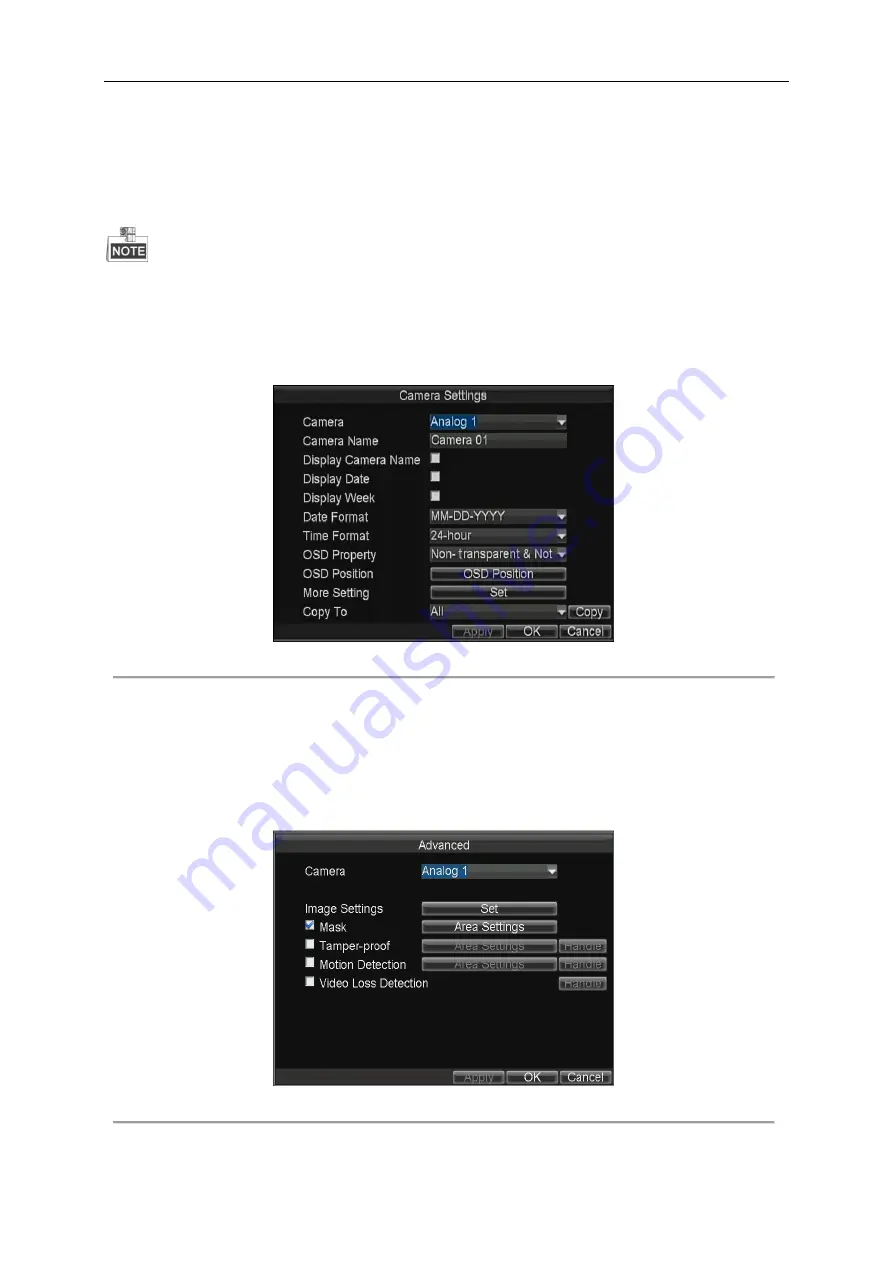
Enter the Camera Settings interface. 

Menu>Other Settings>Camera 


Figure 2. 7


Camera Settings 


2.


Select the camera from the drop-down list. 

3.


Input the camera name as desired in the text field. 

4.


Check the checkboxes to display the camera name, date or week on the live view interface of selected camera. 

5.


Select the date format and time format according to the actual needs, and then select the OSD property. 

6.


Click the 

OSD Position 

button and use the 

F2

 key and 

Direction

 keys on remote control to adjust the OSD position. 

7.


Click the 

Set 

button of More Setting, and you can configure the video parameters, mask area, motion detection, etc. 


Figure 2. 8


More Setting 


Image Settings 

Содержание DS-MP7504

Страница 1: ...Mobile Digital Video Recorder User Manual UD 6L0204D1113A01...

Страница 2: ...os mentioned below are the properties of their respective owners Legal Disclaimer TO THE MAXIMUM EXTENT PERMITTED BY APPLICABLE LAW THE PRODUCT DESCRIBED WITH ITS HARDWARE SOFTWARE AND FIRMWARE IS PRO...

Страница 3: ...ions 1 This device may not cause harmful interference 2 This device must accept any interference received including interference that may cause undesired operation EU Conformity Statement This product...

Страница 4: ...for the transmitter by Industry Canada To reduce potential radio interference to other users the antenna type and its gain should be so chosen that the equivalent isotropically radiated power e i r p...

Страница 5: ...trical safety regulations of the nation and region Please refer to technical specifications for detailed information Input voltage should meet both the SELV Safety Extra Low Voltage and the Limited Po...

Страница 6: ...7504 DS MP7504 GW DS MP7504 GW WI This manual may contain several technically incorrect places or printing errors and the content is subject to change without notice The updates will be added into the...

Страница 7: ...ith the power connection before installation Install antennas of wireless networks and satellite positioning in place with good signal and away from lightning avoiding the coverage or shielding of oth...

Страница 8: ...or etc Specialized aviation connectors ensuring signal stability Ignition startup Delay 0 to 6h shutdown and 24 hour scheduled startup shutdown Wide range power input 8 to 36 VDC Tensile aluminum chas...

Страница 9: ...ser management admin user is allowed to configure the parameters and create many operators Supporting record and search the logs of operation alarm exceptions and information Upgrade system via USB ne...

Страница 10: ...on 17 Chapter 2 Basic Operations 21 2 1 Setting Admin Password 21 2 2 Main Page 21 2 3 User Management 22 2 4 Display Settings 23 2 5 Camera Settings 25 2 6 Preview Settings 27 Chapter 3 Record Settin...

Страница 11: ...ing Alarm Output 50 8 2 3 Configuring Video Tampering Alarm 51 8 2 4 Configuring Video Loss Alarm 52 8 2 5 Handling Exceptions 53 8 2 6 Configuring Alarm Terminal 54 8 3 Firewall Settings 54 8 4 Seria...

Страница 12: ...r Lights green after device starts up properly REC Record indicator Light in green during recording process GNSS GNSS indicator Solid green indicates GNSS module is normal Flashing green indicates pos...

Страница 13: ...nna interface 7 VGA VGA output 8 I O 7 ch high low level signal trigger including 3 ch alarm inputs 4 ch sensor in 1 ch pulse signal input 9 RS232 1 RS 232 interface 10 EXT DEV RS 422 communication in...

Страница 14: ...l in Live View mode 4 Edit 1 Enter the edit status and then delete the character in the front of the cursor 2 It can also be used to tick checkbox 3 In Playback mode it can be used to generate video c...

Страница 15: ...er in the front panel If there is no response after you press any button on the remote follow the procedure below to troubleshoot Steps 1 Go to Menu Settings General More Settings by operating the mou...

Страница 16: ...providing low level signal when the switch closes The wire connection of the device varies from different vehicle ignition switch For detailed time settings of time delay shutdown see Chapter 6 1 Ple...

Страница 17: ...igure 1 5 Connection of Negative Pole Ignition Switch Ignition switch is connected to the negative pole of DC 12 24V of vehicle batteries Please make sure that the connection is correct and then perfo...

Страница 18: ...to avoid error report caused by voltage fluctuation no alarm will be triggered by voltage ranging of 5 6VDC Figure 1 7 Alarm Input Connection 1 5 2 Alarm Output Connection The alarm output interfaces...

Страница 19: ...n 2 Use the screwdriver to loosen and remove the set screw on the 3G and Wi Fi module 3 Pull the 3G module out of the mobile DVR 4 The separate 3G module is shown as the figure 5 Press the yellow butt...

Страница 20: ...l 19 6 Place the SIM card into the SIM card slot correctly as shown in the figure 7 Place the SIM card slot installed with the SIM card back to the 3G module 8 Install the 3G module component back to...

Страница 21: ...Mobile Digital Video Recorder User Manual 20 9 Connect the antenna to the device after the SIM card installation is complete...

Страница 22: ...ters in order to increase the security of your product And we recommend you reset your password regularly especially in the high security system resetting the password monthly or weekly can better pro...

Страница 23: ...Page 2 3 User Management The admin user has all the operation permissions of the device Steps 1 Enter the User Management interface Menu Other Settings User Figure 2 2 User Management 2 Click the Add...

Страница 24: ...elected user and click the Modify button to modify the user information 2 4 Display Settings Purpose You can set the system time select the CVBS output standard enable the password configure the DST s...

Страница 25: ...t the Device No on the remote control every time you use it Brightness of CVBS Adjust the video output brightness Menu Transparency The transparency proportion of the menu displayed on the live view i...

Страница 26: ...gs 2 Select the camera from the drop down list 3 Input the camera name as desired in the text field 4 Check the checkboxes to display the camera name date or week on the live view interface of selecte...

Страница 27: ...e block 7 Press the Enter key on the remote control to save the size of the block 8 You can press the A key on the remote control to clear all the mask areas Up to 4 mask areas can be configured for e...

Страница 28: ...Dwell Time the switch interval of the live view screen The screen will be switched to the next one after the selected dwell time Enable Audio Output Enables disables audio output for the selected vid...

Страница 29: ...Mobile Digital Video Recorder User Manual 28 Figure 2 11 Camera Order 5 Click the Apply button to save the new settings and click OK to exit...

Страница 30: ...st You can view the status free space and capacity 3 Set the Overwrite mode to Yes as No to enable or disable the overwriting function If the HDD is installed correctly and formatted the status is dis...

Страница 31: ...ou can set the video quality as Highest Higher Medium Low Lower and Lowest Frame Rate Frame rate refers to the frequency of the image frame after compression With other parameters constant reduce the...

Страница 32: ...e is set as 5 seconds the camera records the alarm at 9 59 55 Post record After the event finished the video can also be recorded for a certain time For example when an alarm ends at 11 00 if the post...

Страница 33: ...he Handle button of Motion Detection and you can set the arming schedule and alarm linkage actions Perform the following steps to set the arming schedule and alarm triggered linkage actions 1 Select t...

Страница 34: ...ect the alarm triggered recording channel s For other alarm input settings see Chapter 7 2 1 3 Click the Apply button to save the settings and click OK to exit After configuring alarm input enter the...

Страница 35: ...own keys on the remote control to adjust the playback speed 4 Click the Search button and the record files will be displayed on a list Select the record file click the Play button and you can play bac...

Страница 36: ...EXT DEV interface of the mobile DVR Steps 1 Enter the PTZ Settings interface Menu Other Settings PTZ Figure 4 1 PTZ Settings 2 Choose the camera for PTZ setting in the Camera dropdown list 3 Input th...

Страница 37: ...36 Table 4 1 Description of PTZ Control Panel Icon Description Icon Description Icon Description Direction button and the auto cycle button Zoom Focus Iris Zoom Focus Iris Moving speed Light on off W...

Страница 38: ...lect Network Mode as Auto Adjust or 3G Only in the dropdown list Auto the work mode is set as the detected stronger signal Adjust the work mode is set as the 3G mode as long as 3G signal is detected e...

Страница 39: ...eserved 5 2 Wi Fi Settings Purpose You can connect the device to the Wi Fi networks and transmit the data via the Wi Fi Wi Fi function is only supported by DS MP7504 GW WI series Steps 1 Enter the Wi...

Страница 40: ...DHCP and Auto obtain DNS to obtain IP address and DNS server for Wi Fi network automatically 5 Click the Set button of WiFi AP and you can configure the settings of Wi Fi access point Figure 5 5 Wi Fi...

Страница 41: ...Mobile Digital Video Recorder User Manual 40 Figure 5 6 Wi Fi Status Interface...

Страница 42: ...nt platform from the drop down list Figure 6 1 iVMS Platform Settings 3 Configure the following parameters Server IP Input the static IP address of iVMS server Port No The default value is 7660 Device...

Страница 43: ...Mobile Digital Video Recorder User Manual 42 Figure 6 2 Push Mode Platform...

Страница 44: ...from 0 min to 6 hours 4 Optionally check the checkbox of Voltage Protect and then select the voltage limit percent Once the voltage of the device reaches the selected threshold the device will shut d...

Страница 45: ...llite Positioning Settings 2 Select the mode of the Position Module 3 modes of positioning module are selectable RS 232 Obtain data from the satellite positioning module connected through RS 232 inter...

Страница 46: ...sor to the device for obtaining and providing the acceleration speed in 3 axial directions Steps 1 Enter the G Sensor Settings interface Menu Basic Settings G Sensor Figure 7 4 G Sensor Settings 2 Sel...

Страница 47: ...s the driving information of the vehicle including pedal braking turning left right reversing etc Steps 1 Enter the Sensor In Settings interface Menu Basic Settings Sensor In Figure 7 5 Sensor In Sett...

Страница 48: ...lds The IP address of the device should be unique in the network and the default value is 192 0 0 64 The download server IP should be set when you upload the record files to the designate server 3 Cli...

Страница 49: ...ng trigger level arming schedule alarm linkage actions etc Steps 1 Enter the Alarm Input Settings interface Menu Other Settings AlarmIn Figure 8 3 Alarm Input Settings 2 Select the alarm input No inpu...

Страница 50: ...k Copy to copy the current settings to other days in the week Figure 8 4 Arming Schedule 5 Check the checkbox of Handle Type and click the corresponding Set button and you can configure the alarm link...

Страница 51: ...s 2 Select the alarm output No input the alarm name as desired in the text field and then set the alarm duration time Two alarm outputs are available A1 B1 C1 and A2 B2 C2 3 Click the Set button of Sc...

Страница 52: ...he remote control to adjust the position of the red block 3 Press the Enter key on the remote control to save the position of the red block 4 Press the Direction keys on the remote control to adjust t...

Страница 53: ...k Apply to save the new settings and click OK to exit Figure 8 9 Linkage Action of Tamper proof 5 Click Apply to save the new settings and click OK to exit 8 2 4 Configuring Video Loss Alarm Purpose W...

Страница 54: ...Apply to save the new settings and click OK to exit 8 2 5 Handling Exceptions Purpose Exception Settings refer to the handling methods of various exceptions e g HDD Full The HDD is full HDD Error Wri...

Страница 55: ...to save the new settings and click OK to exit The alarm terminal function requires for the cooperation of status display terminal DS 1530HMI For details see the user manual of DS 1530HMI The RS 232 s...

Страница 56: ...Add button to enter the Add IP Address dialog box input the trusted IP address and click OK Figure 8 15 Add IP Address 4 The trusted IP address will be added on the white list Figure 8 16 White List S...

Страница 57: ...remotely by the PC through the network and the protocol of the serial device The RS 485 port can be used for transparent channel only Steps 1 Enter the Serial Port Settings interface to configure the...

Страница 58: ...e 9 2 Management and Maintenance 9 2 1 Upgrading the System Purpose The mobile DVR can be upgraded by local USB device or remote FTP server Upgrading by local USB flash disk Before you start Connect t...

Страница 59: ...rver and the DVR is valid and correct Run the FTP server on the PC and copy the firmware into the corresponding directory of your PC Refer to the user manual of the FTP server to set the FTP server on...

Страница 60: ...Alarm Exception Operation and Information You can also select All as the major type to search all the logs 3 Select the minor type of the logs under the selected major type 4 Specify the start time an...

Страница 61: ...fault Settings 2 Select the restoring type from the following two options Default Restore all parameters except the network including IP address subnet mask gateway MTU NIC working mode default route...

Страница 62: ...le DVR and then click the Import button Reboot the device to activate the new settings after the importing process is complete The configuration file should be stored on the root directory of the USB...

Страница 63: ...he Backup Device interface Menu Maintenance Storage Figure 9 9 Backup Device Interface 2 Select the backup device from the drop down list and you can view the status and the free space capacity of the...

Страница 64: ...4 or more GPS satellite G Sensor G sensor Gravity sensor can sense the change of the accelerated force such as the shaking free falling and lifting And those changes of the accelerated force can be se...

Страница 65: ...lure are as follows a Dialing is not enabled b APN dial number user name and password should be set for 3G VPDN private network c No 3G antenna connected When both the master slave antennas are connec...

Страница 66: ...the polarities of the batteries are not reversed b The batteries are fresh and are not out of power c The remote sensor is not covered or blocked by other object d There are no fluorescent lamps in us...

Страница 67: ...User Manual of Mobile Digital Video Recorder 66...

Отзывы: