background image


10 


4


Terminals and Wirings 

4.1


Terminals 

4.1.1


Indoor Station Terminals 


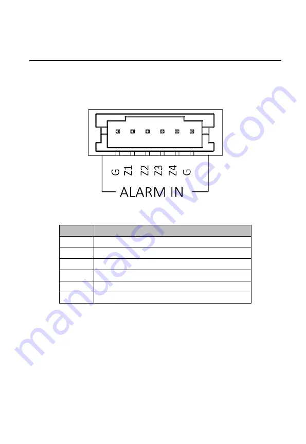
Figure 4-1


Terminals of DS-KH3200-L 

Table 4-1


Descriptions of Terminals and Interfaces 

No. 

Description 

Grounding 

Z1 

Zone Detector Input Terminal 1(Smoke Detector) 

Z2 

Zone Detector Input Terminal 2(Gas Detector) 

Z3 

Zone Detector Input Terminal 3(Door Magnetic) 

Z4 

Zone Detector Input Terminal 4(Active Infrared) 

Grounding 

Содержание DS-KAD312

Страница 1: ...Residential Video Intercom Bundle User Manual ...

Страница 2: ...M EXTENT PERMITTED BY APPLICABLE LAW HIKVISION MAKES NO WARRANTIES EXPRESS OR IMPLIED INCLUDING WITHOUT LIMITATION THE IMPLIED WARRANTIES OF MERCHANTABILITY AND FITNESS FOR A PARTICULAR PURPOSE REGARDING THIS MANUAL HIKVISION DOES NOT WARRANT GUARANTEE OR MAKE ANY REPRESENTATIONS REGARDING THE USE OF THE MANUAL OR THE CORRECTNESS ACCURACY OR RELIABILITY OF INFORMATION CONTAINED HEREIN YOUR USE OF ...

Страница 3: ...he following two conditions 1 This device may not cause harmful interference 2 This device must accept any interference received including interference that may cause undesired operation EU Conformity Statement This product and if applicable the supplied accessories too are marked with CE and comply therefore with the applicable harmonized European standards listed under the EMC Directive 2014 30 ...

Страница 4: ...ct is installed on wall or ceiling the device shall be firmly fixed If smoke odors or noise rise from the device turn off the power at once and unplug the power cable and then please contact the service center If the product does not work properly please contact your dealer or the nearest service center Never attempt to disassemble the device yourself We shall not assume any responsibility for pro...

Страница 5: ...e of sensor at the same time Please use the provided glove when open up the device cover avoid direct contact with the device cover because the acidic sweat of the fingers may erode the surface coating of the device cover Please use a soft and dry cloth when clean inside and outside surfaces of the device cover do not use alkaline detergents Please keep all wrappers after unpack them for future us...

Страница 6: ...Video Audio Distributor Interfaces 12 3 2 Wirings 13 3 2 1 Indoor Station Wiring 13 3 2 2 Door Station Wiring 14 Door Lock Wiring 14 Door Magnetic Wiring 15 Exit Button Wiring 16 External Card Reader Wiring 16 Alarm Device Input Wiring 18 Alarm Device Output Wiring 18 4 DIP Settings 19 4 1 Configure RW 1 19 4 2 Configure RW 2 22 5 Installation 24 5 1 Indoor Station Installation 24 5 1 1 Installati...

Страница 7: ...sidential Video Intercom Bundle User Manual vi 6 1 Getting Started 30 6 2 Initiate Video Intercom 30 6 3 Unlock the Door 30 Appendix 31 Video Audio Distributor Power Supply 31 Door Station Power Supply 33 ...

Страница 8: ...he buildings for improving the living security 1 2 Typical Application Figure 1 1 Typical Application Configure the room number before build the system on the video audio distributor See the 5 DIP Settings for detailed DIP rules The indoor station door station and video audio distributor are connected via network cable transferring analog signal The door station outer door station and master stati...

Страница 9: ...r the power supply connection of door station and video audio distributor Connect LAN2 of door station to the bus input on the video audio distributor via network cable Before configure the device set Digit 8 RW1 as ON to adapt to the current indoor station version ...

Страница 10: ...3 2 ...

Страница 11: ... Description 1 Volume Wheel 2 Power Supply Indicator 3 Alarm Indicator 4 Answer Decline Key 5 Unlock Key 6 Live View Key 7 Management Center Key 8 LCD Display Screen 9 Microphone 10 Arm Disarm Key The Unlock key is valid only when does the indoor station speak with the door station or open the live view of the door station ...

Страница 12: ...5 3 1 2 Rear Panel Figure 3 2 Rear Panel Table 3 2 Components Description No Description 1 Network Interface 24 VDC 2 Reserved 3 Loudspeaker 4 Terminals ...

Страница 13: ...View Figure 3 4 Rear View Table 3 3 Components Description No Description 1 Low Illumination Supplement Light 2 Built in Camera 3 Loudspeaker 4 LCD Display Screen 5 Card Induction Area 6 Keypad 7 Call Button 8 Call Center Key 9 Microphone ...

Страница 14: ...escription 10 TAMPER 3 3 Video Audio Distributor 3 3 1 Front Panel Back Panel Figure 3 5 Front Panel Figure 3 6 Back Panel Table 3 4 Components Description No Description 1 Signal Indicator 2 Power Indicator ...

Страница 15: ...8 3 3 2 Side Panel Figure 3 7 DS KAD312 Side Panel 1 Figure 3 8 DS KAD312 Side Panel 2 Figure 3 9 DS KAD312 Side Panel 3 Table 3 5 Components Description No Description 1 Power Socket ...

Страница 16: ...9 2 Network Interface 3 DIP Switch 4 Serial Port ...

Страница 17: ... DS KH3200 L Table 4 1 Descriptions of Terminals and Interfaces No Description G Grounding Z1 Zone Detector Input Terminal 1 Smoke Detector Z2 Zone Detector Input Terminal 2 Gas Detector Z3 Zone Detector Input Terminal 3 Door Magnetic Z4 Zone Detector Input Terminal 4 Active Infrared G Grounding ...

Страница 18: ...erface Power Supply 4 DC 12V DC 12V Power Supply Input READER A1 12V Power Supply Output A2 GND Grounding A3 W1 Data Input Interface Wiegand Card Reader Data1 A4 W0 Data Input Interface Wiegand Card Reader Data0 A5 BZ Card Reader Buzzer Output A6 ERR Card Reader Indicator Output Invalid Card Output A7 OK Card Reader Indicator Output Valid Card Output A8 TAMP Tamper proof Input of Wiegand Card Read...

Страница 19: ... Power Supply Output C2 GND Grounding C3 NC2 Door Lock Relay Output NC C4 COM2 Grounding Signal C5 NO2 Door Lock Relay Output NO C6 NC1 Door Lock Relay Output NC C7 COM1 Grounding Signal C8 NO1 Door Lock Relay Output NO RS485 D1 GND RS 485 Communication Interfaces D2 485 D3 485 ALARM IN D4 GND Grounding Signal D5 AI4 Alarm Input 4 D6 AI3 Alarm Input 3 D7 AI2 Alarm Input 2 D8 AI1 Alarm Input 1 4 1 ...

Страница 20: ... Bus Output Interface 7 Decoding Output Interface 7 14 Bus Input Interface Interface No 1 to 12 can provide power 24 VDC for indoor station It cannot connect to other device directly Interface No 13 is the bus output interface It supports connect signal amplifier or other video audio distributor Interface No 14 is the bus input interface It supports video and audio input and audio output and conne...

Страница 21: ...14 Figure 4 4 Wiring Description Alarm Input Device The accessed detector should be normally closed 4 2 2 Door Station Wiring Door Lock Wiring Figure 4 5 Door Lock Wiring ...

Страница 22: ...ct electric lock in terminal NO2 COM2 NC2 it is required to set the output of terminal NO2 COM2 NC2 to be electric lock with Batch Configuration Tool or iVMS 4200 Door Magnetic Wiring Figure 4 6 Door Magnetic Wiring To connect the door magnetic it is required to set the output of terminal AI2 to be door magnetic with Batch Configuration Tool or iVMS 4200 ...

Страница 23: ...ld be configured when the card reader is power on please reboot the card reader after configuring the DIP switch The DIP switch description is shown in the following table No Description How to Configure 1 4 Set the RS 485 address ON 1 OFF 0 6 Select Wiegand protocol or RS 485 protocol ON Wiegand OFF RS 485 7 Set the Wiegand protocol It is invalid when setting OFF in 6 ON Wiegand 26 OFF Wiegand 34...

Страница 24: ...17 Figure 4 8 RS 485 Card Reader Wiring Wiegand Card Reader Wiring Figure 4 9 External Card Reader Wiring ...

Страница 25: ...18 Alarm Device Input Wiring Figure 4 10 Alarm Device Input Wiring Alarm Device Output Wiring Figure 4 11 Alarm Device Output Wiring ...

Страница 26: ...s The DIP switch RW1 is used to configure the DIP rules Digit 8 RW1 is used to control the mode Before configure the device set Digit 8 RW1 as ON to adapt to the current indoor station version The DIP switch RW2 is used to configure the start floor No 5 1 Configure RW 1 RW 1 Configuration for Single Distributor When there is only one distributor in the system configure the Digit 1 Digit 2 and Digi...

Страница 27: ... Digit 8 RW1 is used to set the distributor mode ON means the current indoor station version OFF means the former version RW 1 Configuration for More than One Distributor When there are more than 12 households in one floor you need more than one distributor The configuration steps as below Steps 1 Set the digit value of Digit 1 Digit 2 to define the floor No Table 5 3 RW1 Configuration for More th...

Страница 28: ...r mode ON means the current indoor station version OFF means the former version 2 Set the digit value of Digit 4 Digit 4 and Digit 6 to define the room No Table 5 4 RW1 Configuration for More than One Distributor Digit RW1 1 2 3 4 5 6 7 8 Room No of F1 F2 F3 F4 F5 Status OFF OFF OFF 1 12 1 6 1 4 1 3 1 2 ON OFF OFF 13 24 7 12 5 8 4 6 3 4 OFF ON OFF 25 36 13 18 9 1 2 7 9 5 6 ON ON OFF 37 48 19 24 13...

Страница 29: ... the Room No are 13 14 15 16 17 18 19 20 21 22 23 and 24 Table 5 5 RW1 Configuration Example of DS KAD312 for More than 1 Distributor Digit RW1 1 2 3 4 5 6 7 8 Status OFF OFF OFF ON OFF OFF ON 5 2 Configure RW 2 RW2 is used to set the start floor No The configuration as below Set the status ON OFF of each digit to define the start floor The sum of the binary values of digits is the start floor No ...

Страница 30: ...igit2 and Digit4 to be ON as the table below then the start floor No is 11 That is 1 2 8 11 Table 5 7 RW2 Configuration Example of DS KAD312 Digit RW2 1 2 3 4 5 6 7 8 Binary Value 1 2 4 8 16 32 64 128 Status ON ON OFF ON OFF OFF OFF OFF ...

Страница 31: ...pth The dimension of wall mounting plate is shown in Figure 6 1 Figure 6 1 Wall Mounting Plate 6 1 2 Wall Mounting with Junction Box Before you start Make sure the device in the package is in good condition The power supply the indoor station supports is 24 VDC Please make sure your power supply matches your indoor station Make sure all the related equipment is power off during the installation Ch...

Страница 32: ... to the junction box with 2 screws Screws Wall Mounting Plate Junction Box Figure 6 2 Installing the Plate 4 Hook the indoor station to the wall mounting plate tightly by inserting the plate hooks into the slots on the rear panel of the indoor station during which the lock catch will be locked automatically Hooks Slots Slots Lock Catch Figure 6 3 Hooking the Indoor Station to the Plate ...

Страница 33: ...e dimensions above are for reference only The actual size can be slightly different from the theoretical dimension 6 2 2 Wall Mounting with Gang Box Steps 1 Chisel a hole in the wall for inserting the gang box The size of the hole should be larger than that of the gang box The suggested size of hole is 343 5 length 113 5 width 55 5 depth mm 2 Insert the gang box into the hole and fix it with 4 PA4...

Страница 34: ...he Wall 3 Make sure the edges of the gang box align to the wall 4 Route the cables of the door station through the cable hole 5 Put the door station into the gang box Figure 6 6 Install the Door Station 6 Fix the door station to the gang box with 4 crews ...

Страница 35: ... be set on a desk and also support wall mounting The wall mounting steps as below Steps 1 Chisel two holes in the wall The diameter of the hole is 3 mm and the distance between two holes is 136 mm 2 Fix the device onto the wall by it with two PA4 screws Screws Figure 6 8 Wall Mounting 1 3 Installation completes ...

Страница 36: ...29 Figure 6 9 Wall Mounting 2 ...

Страница 37: ...initiates a call to the indoor station Steps 1 Press the Call button on the door station to start a video call to indoor station 2 Press to accept the call and press again to hang up the call The maximum ring duration of the indoor station is 30s The maximum speaking duration is 60s 7 3 Unlock the Door In the following 3 situations you can unlock the door remotely on the indoor station When someon...

Страница 38: ...s two parts to power the video audio distributor power cable and power box as below Figure 7 1 Power Cable Figure 7 2 Power Box To power the video audio distributor you need to connect the cable and power box as below Steps 1 Cut and peal the cable as below ...

Страница 39: ...Peal the Cable The three lines description Color Description Yellow green Grounding Line Brown Fire Line Blue Zero Line 2 Peal the three lines to expose the metal wire and connect to the terminal of the power box accordingly ...

Страница 40: ...cription Terminal Description L Fire Line N Zero Line FG Grounding Line V Negative Pole V Positive Pole 3 Connect the negative pole and positive pole to the video audio distributor accordingly Door Station Power Supply The power adapter for door station as below ...

Страница 41: ...34 Figure 7 5 Power Adapter To power the door station you need to deal with the adapter as below Steps 1 Cut and peal the cable to exposure the metal wire as below Figure 7 6 Cut and Peal the Cable ...

Страница 42: ...35 2 Plug the wire in to the block and fixed Figure 7 7 Connect to the Power Box 3 Connect the block to the door station s power supply input terminal accordingly ...

Страница 43: ...36 UD09863B ...

Отзывы: