


User Manual of Network Video Recorder
84
11.2
Rebuilding Array
Purpose:
The working status of array includes Functional, Degraded and Offline. By viewing the array status, you can take
immediate and proper maintenance for the disks so as to ensure the high security and reliability of the data stored
in the disk array.
When there is no disk loss in the array, the working status of array will change to Normal; when the number of lost
disks has exceeded the limit, the working status of array will change to Offline; in other conditions, the working
status is Disk Loss.
When the logical disk is in Degrade status, you can restore it to Normal by array rebuilding.
11.2.1
Automatically Rebuilding Array
Purpose:
When the logical disk is in Degraded status, the device can start rebuilding the array automatically with the hot
spare disk to ensure the high security and reliability of the data.
Note:
The Auto Recreation function is enabled by default.
Steps:
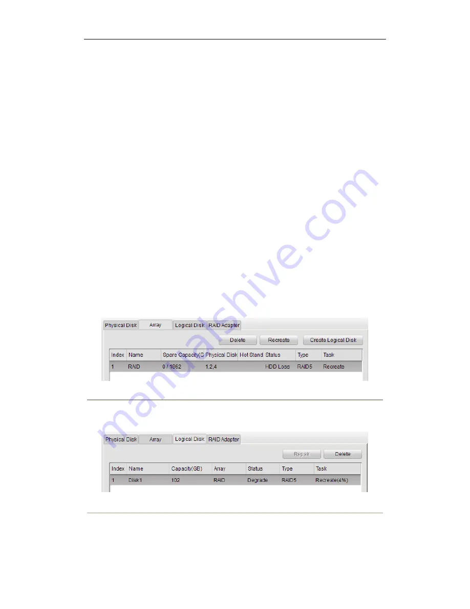
1.
Enter the Array Settings interface. The status of the array is HDD Loss. Since the hot spare disk is configured
and Auto-rebuild function is enabled. The hot spare disk will be automatically used for array rebuilding.
Device Management> Remote Management> HDD >Array Configuration> Array
Figure 11. 13
Array Settings Interface
2.
Enter the Logical Disk interface to view the rebuilding status of the logical disk.
Device Management> Remote Management> HDD >Array Configuration >Logical Disk
Figure 11. 14
Logical Disk Settings Interface
Note:
If there is no hot spare disk after rebuilding, it is recommended to install a HDD into the device and set
is as a hot spare disk to ensure the high security and reliability of the array. For detailed operation guide,
please refer to
steps 12-14 of
Chapter 11.1.2 Manually Creating Array and Logical Disk.
Содержание DS-8508NIST
Страница 1: ...Network Video Recorder User Manual UD 6L0202D1182A01 ...
Страница 11: ...User Manual of Network Video Recorder 10 Chapter 1 Introduction ...
Страница 15: ...User Manual of Network Video Recorder 14 Chapter 2 Network Parameters Configuration ...
Страница 17: ...User Manual of Network Video Recorder 16 Chapter 3 Getting Started ...
Страница 22: ...User Manual of Network Video Recorder 21 Chapter 4 Live View ...
Страница 26: ...User Manual of Network Video Recorder 25 Chapter 5 PTZ Control ...
Страница 30: ...User Manual of Network Video Recorder 29 Chapter 6 Recoding and Capturing Settings ...
Страница 35: ...User Manual of Network Video Recorder 34 Chapter 7 Playback ...
Страница 45: ...User Manual of Network Video Recorder 44 Chapter 8 Alarms Settings ...
Страница 55: ...User Manual of Network Video Recorder 54 Chapter 9 Network Configuration ...
Страница 72: ...User Manual of Network Video Recorder 71 Chapter 10 Camera Settings ...
Страница 78: ...User Manual of Network Video Recorder 77 Chapter 11 RAID Configuration ...
Страница 91: ...User Manual of Network Video Recorder 90 Chapter 12 HDD Settings ...
Страница 96: ...User Manual of Network Video Recorder 95 Figure 12 7 eSATA Information ...
Страница 97: ...User Manual of Network Video Recorder 96 Chapter 13 Local Configuration ...
Страница 99: ...User Manual of Network Video Recorder 98 Chapter 14 Maintenance ...
Страница 110: ...User Manual of Network Video Recorder 109 Appendix ...
Страница 122: ...User Manual of Network Video Recorder 121 ...


