6
English
PRECAUTIONS ON USING CIRCULAR SAW
1. Do not use saw blades which are deformed or cracked.
2. Do not use saw blades made of high speed steel.
3. Do not use saw blades which do not comply with the
characteristics specified in these instructions.
4. Do not stop the saw blades by lateral pressure on the
disc.
5. Always keep the saw blades sharp.
6. Ensure that the lower guard moves smoothly and
freely.
7. Never use the circular saw with its lower guard fixed in
the open position.
8. Ensure that the retraction mechanism of the guard
system operates correctly.
9. Never operate the circular saw with the saw blade
turned upward or to the side.
10. Ensure that the material is free of foreign matter such as
nails.
11. For model C7ST, the saw blades range shall be from
185 mm to 180 mm.
12. Disconnect the plug from the receptacle before carrying
out any adjustment, servicing or maintenance.
13. Do not use abrasive wheels.
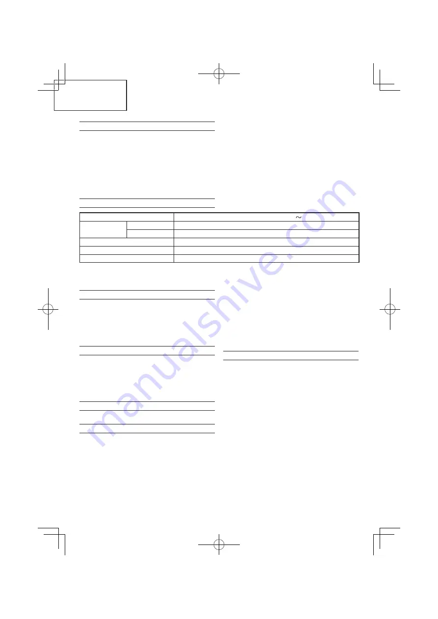
SPECIFICATIONS
Voltage (by areas)*
(110 V, 220 V, 230 V, 240 V)
Cutting Depth
90°
62 mm
45°
47.5 mm
Power Input*
1710 W (1500 W, 1560 W)
No-Load Speed
6000 /min
Weight (without cord)
4.2 kg
* Be sure to check the nameplate on product as it is subject to change by areas.
S4-20% 5 min: Motor service intermittent periodic with start up, with operating time at constant load at the power
indicated of one minute and a response time of four minutes.
STANDARD ACCESSORIES
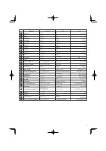
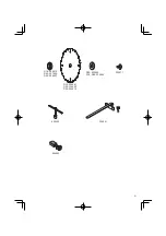
(1) Saw Blade (Dia. 185 mm) (mounted on tool ) ..............1
(2) Box wrench ...................................................................1
(3) Guide ............................................................................1
(4) Wing-bolt ......................................................................1
(5) Spring ...........................................................................1
Standard accessories are subject to change without
notice.
OPTIONAL ACCESSORIES (sold separately)
(1) Dust Collector Set
Connect the suction hose to collect saw dust with the
vacuum cleaner (see
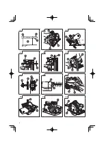
Fig. 12
).
(2) Washer (A) ..............for 16 mm (Hole dia. of saw blade)
............. for 20 mm (Hole dia. of saw blade)
............. for 30 mm (Hole dia. of saw blade)
Optional accessories are subject to change without notice.
APPLICATION
Cutting various types of wood.
PRIOR TO OPERATION
1. Power source
Ensure that the power source to be utilized conforms
to the power requirements specified on the product
nameplate.
2. Power switch
Ensure that the power switch is in the OFF position. If
the plug is connected to a receptacle while the power
switch is in the ON position, the power tool will start
operating immediately, inviting serious accident.
3. Extension cord
When the work area is removed from the power source,
use an extension cord of sufficient thickness and rated
capacity. The extension cord should be kept as short as
practicable.
4. Prepare a wooden workbench. (Fig. 1)
Since the saw blade will extend beyond the lower surface
of the lumber, place the lumber on a workbench when
cutting. If a square block is utilized as a workbench,
select level ground to ensure it is properly stabilized. An
unstable workbench will result in hazardous operation.
CAUTION
To avoid possible accident, always ensure that the
portion of lumber remaining after cutting is securely
anchored or held in position.
ADJUSTING THE POWER TOOL PRIOR TO USE
1. Adjusting the cutting depth
To adjust cutting depth, loosen the lever (A) and, while
holding the base with one hand, move the main body up
and down to obtain the prescribed cutting depth. After
adjusting to the prescribed cutting depth, tighten the
lever (A) securely (
Fig. 2
).
CAUTION
Should this lever (A) remain loosened, it will create a
very hazardous situation. Always thoroughly clamp it.
2. Adjusting the angle of inclination
By loosening the lever (A) at the scale, the saw blade
can be inclined up to maximum angle of 45° against the
base.
The angle of inclination can also be regulated by
loosening the lever (A) at the scale (
Fig. 3
).
CAUTION
It is very hazardous to allow this lever (A) to remain
loosened. Always thoroughly clamp it.
3. Regulating the guide
The cutting position can be regulated by moving the
guide to the left or right after loosening its wing bolt.
The guide can be mounted on either the left or the right
sides (
Fig. 4
).
Содержание C 7ST
Страница 2: ...1 2 3 4 5 6 7 8 9 10 11 12 2 43 6 mm 17 mm 0 45 ...
Страница 22: ...22 ...
Страница 23: ...23 ...
Страница 24: ...906 Code No C99194837 F Printed in China Shinagawa Intercity Tower A 15 1 Konan 2 chome Minato ku Tokyo Japan ...


