14
NEW LEADER
Please Give Part No., Description
& Unit Serial No.
L4000G4
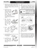
307074-D
Page Rev. A
6.
Do not
weld on
v e h i c l e
f r a m e
as such
we l d i n g
can lead
to fatigue
cracking
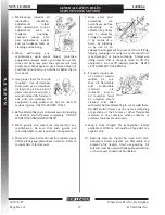
and must be avoided. When drilling holes in
frame member, drill only through the vertical
web portions do not put holes in top or
bottom flanges. Refer to truck manufacturer’s
recommendations.
7.
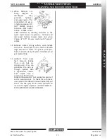
Be sure that welds between mounting bars and
sill or between mounting angles and spreader
cross sills are sound, full fillet welds. Center
mounting angles so that good fillet welds can
be made on three sides—and edge bead weld is
not a satisfactory weld for this service. Use 309
rod/wire for carbon steel and 409 steel. On 304
stainless steel bodies use SAE grade 5 bolts—
welding is recommended if type 308 welding rod
is available.
8.
Install controls so that they are located of
convenient use. Position them so that they do not
interfere with any vehicle control and that they
do not interfere with driver or passenger or with
access to or exit from the vehicle.
9.
Check for vehicle visibility, especially toward the
rear. Reposition or add mirrors so that adequate
rearward visibility is maintained.
10.
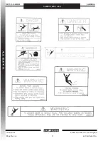
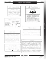
Add Caution, Warning, Danger and Instruction
decals as required. Peel off any label masking
which has not been removed.
11.
Install all guards as required.
12.
Check installation completely to be sure all
fasteners are secure and that nothing has been
left undone.
1.
The selection of the vehicle on which a spreader
body is to be mounted has important safety
aspects. To avoid overloading:
a.
Do not mount spreader on a chassis which,
when fully loaded with material to be
spread, will exceed either the Gross Axle
Weight Rating (GAWR) or the Gross Vehicle
Weight Rating (GVWR) for the chassis.
b.
Do install the spreader only on a vehicle
with cab-to-axle dimension recommended
for the spreader body length shown.
2.
Follow mounting instructions in the Installation
section of this manual. If mounting conditions
require deviation from these instructions refer to
factory.
3.
When making the installation, be sure that the
lighting meets Federal Motor Vehicle Safety
Standard (FMVSS) No. 108, ASABE S279 and all
applicable local and state regulations.
4.
When selecting a PTO to drive hydraulic pump, do
not use a higher percent speed drive than indicated
in the Installation section of this manual. Too high
a percent PTO will drive pump at excessive speed,
which can ruin the pump, but more importantly,
will overheat the hydraulic oil system and increase
the possibility of fire.
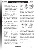
5.
W h e n
truck frame must
be shortened, cut
off only the portion
that extends behind
rear
shackle
in
accordance with the
truck manufacturer’s
recommendations. If
a torch is used to make
the cut, all necessary precautions should be taken
to prevent fire. Cuts should not be made near
fuel tanks and hydraulic oil reservoirs, fuel, brake,
electric or hydraulic lines and such lines should
be protected from flame, sparks or molten metal.
Tires should be removed if there is any chance
of their being struck by flame, sparks or molten
metal. Have a fire extinguisher handy.
GENERAL SAFETy RULES
INSTALLATION INSTRUCTIONS
S
A
F
E
T
y
All manuals and user guides at all-guides.com


