8
A
R
:
• Insula on material used as part of wall pass-through system shall be of noncombus ble material and shall have a
thermal conduc vity of 1.0 Btu-in./hr- - °F (4.88 kg-cal/hr-m - °C) or less.
• All clearances and thicknesses are minimums; larger clearances and thicknesses shall be permi ed.
• Any material used to close up an opening for the connector shall be of noncombus ble material.
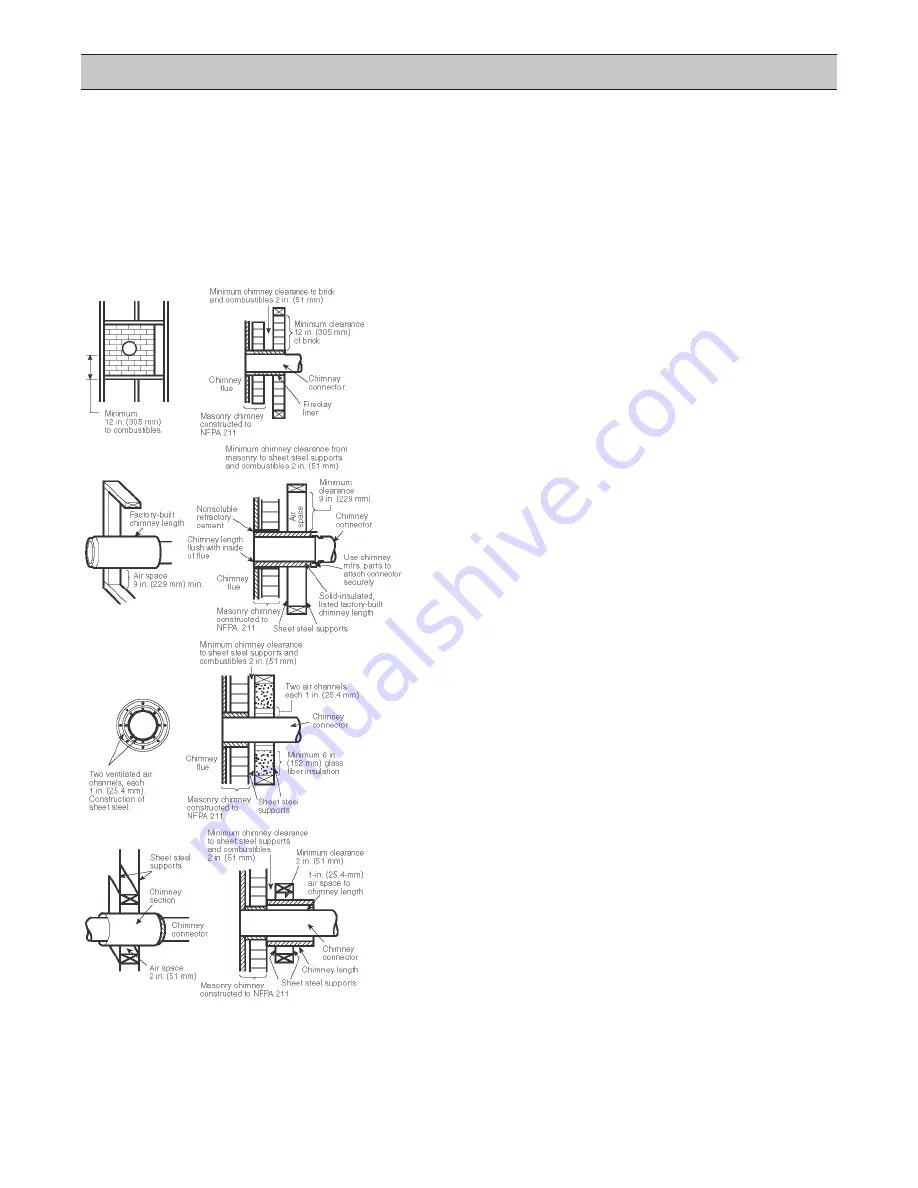
• A connector to a masonry chimney, except for System B, shall extend in one con nuous piece through the wall
pass-through system and the chimney wall to the inner face of the
fl
ue liner, but not beyond.
• Minimum 3.5 inch (90mm) thick brick masonry wall framed into com-
bus ble wall with a minimum of 12 inch (305mm) brick separa on
from clay liner to combus bles. Fireclay liner (ASTM C 315, Standard
Speci
fi
ca on for Clay Fire Linings, or equivalent), minimum
⁵
⁄
₈
inch
(16mm) wall thickness, shall run from outer surface of brick wall to,
but not beyond, the inner surface of chimney
fl
ue liner and shall be
fi
rmly cemented in place.
• Solid-insulated, listed factory-built chimney length of the same inside
diameter as the chimney connector and having 1 inch (25.4mm) or
more of insula on with a minimum 9 inch (229mm) air space between
the outer wall of the chimney length and combus bles. The inner end
of the chimney length shall be
fl
ush with the inside of the masonry
chimney
fl
ue and shall be sealed to the
fl
ue and to the brick masonry
penetra on with non-water-soluble refractory cement. Supports shall
be securely fastened to wall surfaces on all sides. Fasteners between
supports and the chimney length shall not penetrate the chimney liner.
• Sheet steel chimney connector, minimum 24 gauge [0.024 inch (0.61
mm)] in thickness, with a ven lated thimble, minimum 24 gauge [0.024
inch (0.61mm)] in thickness, having two 1 inch (25.4mm) air channels,
separated from combus bles by a minimum of 6 inch (152mm) of glass
fi
ber insula on. Opening shall be covered, and thimble supported with
a sheet steel support, minimum 24 gauge [0.024 inch (0.61mm)] in
thickness. Supports shall be securely fastened to wall surfaces on all
sides and shall be sized to
fi
t and hold chimney sec on. Fasteners used
to secure chimney sec on shall not penetrate chimney
fl
ue liner.
• Solid-insulated, listed factory-built chimney length with an inside di-
ameter 2 inch (51mm) larger than the chimney connector and having
1 inch (25.4mm) or more of insula on, serving as a pass-through for a
single wall sheet steel chimney connector of minimum 24 gauge [0.024
inch (0.61mm)] thickness, with a minimum 2 inch (51mm) air space
between the outer wall of chimney sec on and combus bles. Mini-
mum length of chimney sec on shall be 12 inch (305mm). Chimney
sec on concentric with and spaced 1 inch (25.4mm) away from con-
nector by means of sheet steel support plates on both ends of chimney
sec on. Opening shall be covered, and chimney sec on supported on
both sides with sheet steel supports of minimum 24 gauge [0.024 inch
(0.61mm)] thickness. Supports shall be securely fastened to wall sur-
faces on all sides and shall be sized to
fi
t and hold chimney sec on.
Fasteners used to secure chimney sec on shall not penetrate chimney
fl
ue liner.
C
C
• Special care must be exercised to ensure that all chimney clearances to combus bles meet current standards.
• Exis ng chimneys should be inspected to ensure that clearances to combus bles are in compliance.
• Factory-built chimney clearances are de
fi
ned in the manufacturer's installa on instruc ons.
• Masonry chimney clearances to combus bles are described in the current NFPA standard 211.
• Clearances to combus bles may vary for indoor and outdoor installa ons.
C
T
D
• Special
construc on techniques are required to ensure safe connec on to a chimney through a combus ble
wall. Seek the current version of NFPA standard 211 and the approval of the local Authority Having Jurisdic on.
C
C
T
D


