background image

USER MANUAL

Page 6/ 16

HLK-B10

4. Basic Functional Description

4.1. Two working states of the module

HLK-B10 module has two working states: transmission mode and AT command mode.

In AT command mode, the command can be sent to the module through serial port to

configure the parameters of the module and query the information of the module.

In transmission mode, the module will transmit the serial port data and Bluetooth

connection data in two-way.

Starting module, the default is the transmission mode; there is no affect to the Bluetooth

connection state when exit transmission mode into AT mode. The serial port-Bluetooth data

transmission is paused, and the data received by the serial port is processed by the current

AT instruction. After the transmission is restored, the data transmission will continue.

4.2. Function Keys and Status Indicators

4.2.1. State output pin

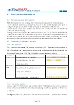
The 16th foot of the module P02 is output pin for state LED

When this pin is connected to

the LED cathode, the current working status of the module can be displayed through the
light and off status of the LED. The LED display status is defined as follows

AT command
mode

Intermittent flash

every 2 fast flash

Transmission
mode

No connect Bluetooth

slow flash

bright 1s turn off 1s

Connect Bluetooth

Long bright and short off

bright 5s turn off 100ms

Restore default settings

Continuous flash

4.2.2. Function key input pin

Module 5 pin P 11 for function key input pin. that is ES/Del pin, a key can be connected

between this pin and GND,The functions corresponding to different operation of the key are
as follows

Short press

50ms

1s

the module will exit transmission mode.

switch to AT command

Содержание HLK-B10

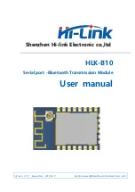
Страница 1: ...Shenzhen Hi link Electronic co ltd HLK B10 Serial port Bluetooth Transmission Module User manual Version V1 0 Revise Date 2019 8 12 Rights reserved ShenZhen Hi link Electronic co Ltd...

Страница 2: ...RANSMISSION AND AT COMMAND MODE 8 4 3 1 SWITCH FROM TRANSMISSION TO AT INSTRUCTION MODE 8 4 3 2 FROM AT INSTRUCTION MODE TO TRANSMISSION MODE 8 5 AT COMMAND 9 5 1 AT COMMAND FORMAT 9 5 2 AT COMMAND LI...

Страница 3: ...connect the customer s equipment or MCU s serial port to the module and the module will automatically complete the two way data transmission between the serial port and Bluetooth which just like a bri...

Страница 4: ...input pin Low level efficiency 2 P07 I O GPIO7 3 P31 I O ADC CH1 4 P10 I O PWM 0 20mA 5 P11 I O Keystroke input pin Low level efficiency 6 P12 I O PWM 2 7 P13 I O PWM 3 8 3 3V P Module power supply 3...

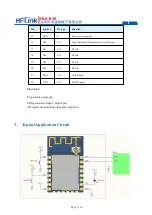
Страница 5: ...te indicate LED output Low level efficiency 17 P03 I O GPIO3 18 P04 I O GPIO4 19 P05 I O GPIO5 20 P06 I O GPIO6 21 RXD I O UART input 22 TXD I O UART output Illustration P represents power pin I O rep...

Страница 6: ...n After the transmission is restored the data transmission will continue 4 2 Function Keys and Status Indicators 4 2 1 State output pin The 16th foot of the module P02 is output pin for state LED When...

Страница 7: ...nd mode In transmission mode the serial port receives special format data to automatically exit the transmission When you are about to exit transmission mode the serial port pauses the input 200ms to...

Страница 8: ...send out AT DEVNAME HLK B10 received AT DEVNAME HLK B10 OK Query class command format AT x x represents parameter name of the query represent parameter value Returned value AT x example send out AT D...

Страница 9: ...ault settings Send out AT DEFAULT 1 received OK 6 Bluetooth Connection Method As a Bluetooth 5 0 slave device HLK B10 module provides a fff0 service and Bluetooth data transmission is mainly based on...

Страница 10: ...SB to serial port function After the computer is connected through a USB cable the serial port of the module can be connected through a USB to serial port and the serial port of the module is not requ...

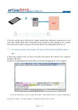
Страница 11: ...phone APP as it is 7 3 An example of data Transmission Test between Serial Port and Mobile phone APP Connect the module to the test board correctly and connect the module to the computer through USB c...

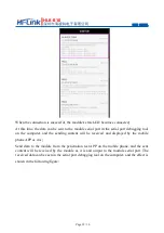
Страница 12: ...the computer and the sending content will be received and displayed by the mobile phone APP as it is Send data to the module from the penetration test APP on the mobile phone and the sent content wil...

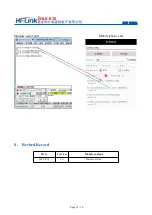
Страница 13: ...USER MANUAL Page 13 16 HLK B10 Module serial port Mobile phone end 8 Revised Record Date Version Modify content 2019 8 12 1 0 Initial version...

Страница 14: ...6 HLK B10 9 Technical Support and Contact Information SHENZHEN HI LINK ELECTRONIC CO LRD ADD 3F Cai Yue Building West No 24 Liu Xian Avenue Long Hua district Shenzhen 518131 TEL 0755 23152658 83575155...

Страница 15: ...nal testing Part 15 Subpart B disclaimer To ensure compliance with all non transmitter functions the host manufacturer is responsible for ensuring compliance with the module s installed and fully oper...

Страница 16: ...ipment into an outlet on a circuit different from that to which the receiver is connected Consult the dealer or an experienced radio TV technician for help NOTE 2 Any changes or modifications to this...

Отзывы: