


14
6.8
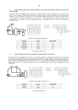
System of heating hot water with solar collectors. Additionally, a system activating the heating of hot water after the boiler achieves a
required temperature
Controlling the collector pump is analogous to that in the system no. 1, described in paragraph 6.1Pump K operates with the use of temperature sensors
T3 and T4, and an auxiliary control coefficient ∆T2. When the sum of temperature T4 and the auxiliary control coefficient ∆T2 is below the value of
temperature T3, pump K is switched on. When the sum of T4 + ∆T2 is above the temperature measured by sensor T3, pump K switches off. In order to
prevent the system from an oscillatory on-switching of pump K when the sum of T4 + ∆T2 parameters is equal to temperature T3, hysteresis control has
been implemented, with the value of 2°C. In this system, calculating collector power is not possible because sensor T3 measures the temperature of the
return from the boiler.
Schematic and electric diagram of installation no. 8
Parameter
Range
Default settings
ΔT1 [°C]
5 - 15
8
ΔT2 [°C]
5 - 15
5
T2max [°C]
10 - 85
65
T4max [°C]
10 - 35
65
Pump regulation
Yes / No
Yes
Cooling
Yes / No
No
List of parameters for diagram no. 8
6.9
A system allowing to control pumps operating with collector batteries situated on various directions
Controlling the collector pump is analogous to that in the system no. 1, described in paragraph 6.1. Controlling pump K is done with the use of sensors T2 and
T3, and the basic control coefficient ∆T1. When the sum of temperature from sensor T2 and the control coefficient ∆T1 is below the value of temperature T3,
output O3 is switched on controlling pump K, which is switched on. When the sum of T2 + ∆T1 exceeds the temperature T3 value, pump K is switched off. In
order to prevent the valve from oscillating on and off when the sum of T2 + ∆T1 parameters is equal to temperature T3, hysteresis control has been
implemented, with the value of 2°C. In this system, calculating collector power is not possible because sensor T3 measures the temperature of the second
collector battery.
Schematic and electric diagram of installation no. 9
Parameter
Range
Default settings
ΔT1 [°C]
5 - 15
8
T2max [°C]
10 - 85
70
Cooling
Yes / No
No
List of parameters for diagram no. 9
Содержание Geco G422-P01
Страница 1: ...1 G422 P01 Controller for a solar collector system...
Страница 2: ...2 software version 2 00a...


