


13
6.6
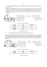
A system of two solar heaters, with heating priority for heater B
Heating using heater B collectors is analogous to that in the system no. 1, described in paragraph 6.1. When a given temperature is reached in heater B, or
temperature T2max is exceeded, the controller automatically starts heating water in tank A, switching on output O2 and redirecting valve U in the direction of
heater A. When temperature in tank A is reached or maximum temperature T4max is exceeded, the controller switches the valve back in the direction of tank B
and switches off the collector pump. The controller switches the pump off also when temperatures T2 and T4 exceed, respectively, maximum values of T2max
and T4max. When the controller is heating water in tank A, once every hour, for a duration of 5 minutes, the controller forces a switch-off of the collector pump
in order to check the conditions in heater B and switch control back to priority tank B, if it is necessary to heat the water in it. Sensor T3 is used to measure the
momentary power of the collector. It is not necessary in the system, but its absence will result in power not being displayed on the screen. Absence of the
remaining sensors will cause the alarm to switch on.
Schematic and electric diagram of installation no. 6
Parameter
Range
Default settings
ΔT1 [°C]
5 - 15
8
T2max [°C]
10 - 85
65
T4max [°C]
10 - 70
65
Pump regulation
Yes / No
Yes
Cooling
Yes / No
No
List of parameters for diagram no. 6
6.7
A system allowing the collectors to cooperate with a buffer accumulator used to cooperate with central heating
Controlling the collector pump is analogous to that in the system no. 1, described in paragraph 6.1. Pump K operates with the use of temperature sensors
T3 and T4, and an auxiliary control coefficient ∆T2. When the sum of temperature T4 and the auxiliary control coefficient ∆T2 is below the value of
temperature T3, pump K is switched on. When the sum of T4 + ∆T2 is above the temperature measured by sensor T3, pump K switches off. In order to
prevent the system from an oscillatory on-switching of pump K when the sum of T4 + ∆T2 parameters is equal to temperature T3, hysteresis control has
been implemented, with the value of 2°C. In this system, calculating collector power is not possible because sensor T3 measures the temperature of the
return from the boiler. Sensor T3 is used to measure the momentary power of the collector. It is not necessary in the system, but its absence will reflect in
that power will not be displayed on the screen. Absence of the remaining sensors will cause the alarm to switch on.
Schematic and electric diagram of installation no. 7
Parameter
Range
Default settings
ΔT1 [°C]
5 - 15
8
ΔT2 [°C]
5 - 15
5
T2max [°C]
10 - 85
65
Pump regulation
Yes / No
Yes
Cooling
Yes / No
No
List of parameters for diagram no. 7
Содержание Geco G422-P01
Страница 1: ...1 G422 P01 Controller for a solar collector system...
Страница 2: ...2 software version 2 00a...


