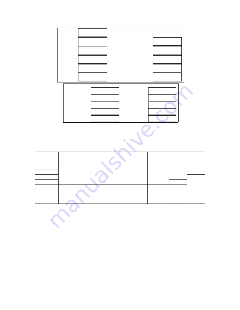
background image


11

Max.Pressure PS

Max Temperatur

Volume V

Min. Temperatur

Volumen

Min. Temp. Tmin.

HYD.Test Pressure Ph

Hydrostaticher Testdruck

Maximaler Druck

Max.Temp.Tmax.

Datum

Design Code
Designcode

Serial No
Seriennummer

Act. Thick Vessel

Manufacture Date

Corrosion All
Korrosionsanteil

Wandstärke/Druckbehälter

Bar

Bar

°C

°C

lt

mm

mm

En 286-1


100

  -10

TYP

TYPE

DRUCK

PRESSURE

KAPAZITÄT
CAPACITY

LEISTUNG

NOM.POWER

NENNSTROM

CURRENT

GEWICHT

WEIGHT

SERIENNUMMER

SERIAL NO

HERSTELLUNGSDATUM

MANUF. DATE

VOLTAGE

FREQUENCY

ELEKTRISCHER
SCHALTPLAN
ELEC.DIAG. NO

bar

m /dak

m /min

A

kg.

3

3

~

kW

NENNSPANNUNG

FREQUENZ

            V3Ph

   Hz

COMPRESSOR
PLATE

OIL TANK
PLATE


3.2 DIMENSIONS 


MODEL 

W X L X H  (mm) 

RECEIVER 

VOLUME 

(l) 

WEIGHT 

(kg) 

NOISE  

LEVEL 

(dBa) 


WITH RECEIVER 

WITHOUT RECEIVER 

HGS 2 

1900 X 642 X 1178 

900 X 642 X 830 

200 

260 

68 

HGS 3 
HGS 4 

69 

HGS 5 

300 

HGS 5D 

1820 X 550 X 1178 

1000 X 550 X 625 

200 

280 

HGS 7 

1900 X 645 X 1500 

1000 X 645 X 830 

500 

310 

HGS 11 

1900 X 650 X 1550 

1150 X 650 X 910 

500 

340 

HGS 15 

350 


Содержание HGS 2-15

Страница 1: ...HGS 2 15 OPERATOR HANDBOOK ...

Страница 2: ......

Страница 3: ...OR LAYOUT DIRECT DRIVE 8 3 CHAPTER TECHNICAL DATA 3 1 TECHNICAL DATA 10 3 2 DIMENSIONS 11 4 CHAPTER OPERATION 4 1 GENERAL 12 4 2 FUNCTION EXPLANATIONS 12 4 3 OPERATION OF THE COMPRESSOR 13 4 4 START UP COMMISIONING 14 4 5 DAILY OPERATION 15 4 6 STOPPING THE COMPRESSOR 15 5 CHAPTER MAINTENANCE 5 1 GENERAL 16 5 2 DAILY MAINTENANCE 16 5 3 PERIODIC MAINTENANCES 16 5 4 MAINTENANCE INSTRUCTIONS 17 COMPR...

Страница 4: ......

Страница 5: ...s humidity etc type of corrosive environmental factors 9 Stop the compressor before removal of any connection or equipment filter etc and make sure that internal pressure is completely discharged check that the oil receiver is empty and the pressure gauge value is at 0 In order to avoid any damage and injury after shutting off the compressor wait for the decrease of the foam of the oil in oil rece...

Страница 6: ...unit cooler separator oil filter etc operating inside the compressor may heat up that may cause burns in case of contact In the meanwhile oil is hot during operation Do not contact such surfaces 9 If you see oil splash from any place do not try to prevent this by your hand Only stop the compressor by pressing emergency stop button and switch off the main switch 9 Do not put your head or your hands...

Страница 7: ... COMPRESSOR 9 Lift the compressor by forklift The forklift blade entry place at the bottom is easy to see 9 Before lifting the compressor make sure that the forklift blade is well balanced 9 Ensure that he forklift does not lift the compressor excessively move slowly and carefully 9 If you should lift the compressor with palette ensure that the compressor is fixed to the palette first Never lift t...

Страница 8: ...urposes Do not exceed the pressure value indicated on the name plate 9 The floor on which the compressor is mounted should be capable of carrying the weight of compressor and should be flat 9 Technical specifications of the receiver are written on the name plate 9 Water must be discharged from the valve beneath the receiver for daily maintenance 9 Without any written approval of the factory do not...

Страница 9: ...0 C Do not place your compressor where the temperature is less than 2 C and if necessary heat the compressor room 9 If you think that there will not be sufficient amount of air flow in the room of operation it is necessary to make room ventilation or you must discharge the outgoing hot air the compressor to outside When doing this the outgoing hot air of compressor should not return For this reaso...

Страница 10: ...Main Fuse data are given for 380V 400V AC Power Supply and maximum 25m Power Cable length If the Power Supply Voltage is different and or Power Cable length is longer than 25m than you may need to use different Main Fuses and or larger cross section area Power Cables In this case please apply to our Service Department 2 4 COMPRESSOR LAYOUT BELT DRIVEN MODELS As shown in the figure compressor has m...

Страница 11: ...TAKE FILTER COMPRESSOR UNIT MOTOR OIL RECEIVER OIL DISCHARGE VALVE NOTE DEPENDING ON THE MODEL COOLER MAY BE ON THE TOP OR SIDE THE ABOVE FIGURE WAS USED FOR GENERAL VIEW 2 5 COMPRESSOR LAYOUT DIRECT DRIVE MODELS ...

Страница 12: ...9 COOLER SEPERATOR PRESSURE SWITCH CONTROLLER UNIT FAN OIL FILTER COMPRESSOR UNIT MOTOR Note For easy follow electric box was not shown on the figure ...

Страница 13: ...ENSIONS mm MAIN MOTOR TYPE SERIAL NO COMPRESSOR TYPE SERIAL NO MAIN MOTOR PLATE DATA rpm kW A OIL OIL CAPACITY L OIL FILTER PRE FILTER INTAKE FILTER BELT SEPERATOR FILTER AIR RECEIVER TYPE SERIAL NO AIR RECEIVER MAX WORKING PRESS Bar AIR RECEIVER TEST PRESSURE Bar AIR RECEIVER MANUFACTURE DATE 9 The above mentioned data are definition oriented and our company reserves the right to make any modific...

Страница 14: ...G NOM POWER NENNSTROM CURRENT GEWICHT WEIGHT SERIENNUMMER SERIAL NO HERSTELLUNGSDATUM MANUF DATE VOLTAGE FREQUENCY ELEKTRISCHER SCHALTPLAN ELEC DIAG NO bar m dak m min A kg 3 3 kW NENNSPANNUNG FREQUENZ V3Ph Hz COMPRESSOR PLATE OIL TANK PLATE 3 2 DIMENSIONS MODEL W X L X H mm RECEIVER VOLUME l WEIGHT kg NOISE LEVEL dBa WITH RECEIVER WITHOUT RECEIVER HGS 2 1900 X 642 X 1178 900 X 642 X 830 200 260 6...

Страница 15: ...trols the air suction and provides machine run on load or unload CONTROL SOLENOID VALVE When the compressor reaches to adjusted pressure values it controls the air that goes to intake valve and makes the compressor operate at unload PRESSURE SWITCH If the pressure in air vessel exceeds the set value the pressure switch stops the compressor It is placed on the left side of electric board SAFETY VAL...

Страница 16: ... the oil temperature reaches the specific value In this case oil goes from separator tank directly to oil filter 9 and from there to airend unit When the oil temperature reaches the required value 71 85 C thermal valve closes the line in between separator tank and oil filter And it ensures the oil to flow into cooler side of combicooler 8 After cooling process oil sent to oil filter then the filte...

Страница 17: ...e If you want to start up the compressor by yourself read this handbook very carefully Performing an erroneous process may be hazardous for your compressor facility or the personnel working in this region 9 Check the oil level On the oil receiver body there is a transparent hose for easily seeing the oil level on the belt driving models Check the oil level when compressor is at the stop position D...

Страница 18: ...g 9 All the functions and reliability of your compressor has been tested after manufacture The above mentioned information of commissioning is against the probability of your compressor being damaged during transportation If you can not see a failure status after all controls you can start up the compressor 4 5 DAILY OPERATION At normal days before running your compressor you may perform some simp...

Страница 19: ... review the section 7 TROUBLESHOOTING part 9 During operation check the failure warnings and operating values from the control panel 9 Discharge the water collected in the air receiver by opening the valve under the tank 5 3 PERIODIC MAINTENANCE For performing the periodic maintenance read thoroughly the maintenance instructions to be mentioned in the following pages WEEKLY MAINTENANCE 9 Clean the...

Страница 20: ... property of separation from water and air is outstandingly developed and as it has a good oxidation resistance it is an ideal oil to be used in screw type compressors Oxidation resistance High temperatures are formed during compression of air The oil that does not have oxidation resistance starts to leave oxidized impurities at some points This causes decrease in efficiency and increase in mainte...

Страница 21: ...for internal pressure discharge and oil to strain down 9 Remove the oil charging plug 9 Discharge the oil completely by opening the oil discharge valve After the oil flow is finished close the oil discharge valve 9 Fill the new oil 9 Replace the oil filter by new one and manually tighten 9 Complete the connections by installing oil charging plug 9 Run the compressor for a few minutes for checking ...

Страница 22: ... INTAKE FILTER REPLACEMENT o Intake filter keeps the thin dust inside the suction air Filter change depends on the ambient conditions and maintenance but should be changed every 2000 hours or 6 months BELT DRIVEN MODELS DIRECT DRIVEN MODELS For replacing the intake filter 9 Switch off the compressor By removing the nut that is tightening the filter top cover remove the top cover and filters 9 Clea...

Страница 23: ...ENGE LINE BELT DRIVEN MODELS DIRECT DRIVEN MODELS SCAVENGE LINE SCAVENGE ORIFICE o When the separator filter is separating the air from oil some quantity of oil penetrates into the filter element This oil is recovered to the system by oil return line o When the compressor is operating at load the oil flow from the scavenge hose should be seen o If the orifice in the scavenge line gets blocked the ...

Страница 24: ...ly o Do not change the pressure related with the compressor operation thermal current and time adjustments When the adjusted value is exceeded the motor current will increase as the load will increase This situation may cause burning down of your motor o Do not use products like the belts separator and oil filters that have complete their service life The maintenance activities that are no perform...

Страница 25: ...DOES NOT OPERATE 1 NO ELECTRICAL POWER CHECK THE VOLTAGE FROM INPUT TERMINAL BLOCK 2 CONTROL OR INPUT FUSE IS BLOWN MAIN SWITCH TRIPPED CHECK THE FUSES 3 VOLTAGE IS LOW UNSTABLE OR OPPOSITE OBSERVE THE WARNING ON THE PHASE CONTROL RELAY 4 COMPRESSOR HAS STOPPED FOR ANY KIND OF FAILURE OBSERVE THE WARNING ON THE CONTROL PANEL 5 OPERATOR TRY TO START WHEN THE DISCHARGING DELAY TIME AFTER STOPPING TH...

Страница 26: ...H THE MAXIMUM PRESSURE CLOSE THE OUTLET VALVE OBSERVE THAT THE PRESSURE IS INCREASING AND THE COMPRESSOR WORKING OFFLOAD IF THE PRESSURE DOES NOT RISE THERE MUST BE ANOTHER FAILURE INFORM THE SERVICE 2 THE INTAKE FILTER CLOGGED CHECK THE INTAKE FILTER BY STOPPING YOUR COMPRESSOR REPLACE IF CLOGGED 3 THE INTAKE VALVE IS DEFECTED THIS MAY HAPPEN IN CASES WHEN THE INTAKE VALVE CLAPET GETS STUCK AND O...

Страница 27: ...AY BE SMALLER THAN THE COMPRESSORS INTAKE AREA THE HOT AIR OUTLET CAN NOT BE DISCHARGED OUT OF COMPRESSOR ROOM HEALTHILY THE COOLER MAY BE DIRECTLY SUBJECT TO SUN LIGHT AND THERE MAY BE STRONG WIND OPPOSITE TO THE HOT AIR OUTLET CHECK AND TAKE NECESSARY PRECAUTIONS 3 OIL LEVEL IS LOW CHECK THE OIL FILTER AND FILL IF NECESSARY 4 THE OIL FILTER IS CLOGGED REPLACE THE OIL FILTER 5 THE LIFE OF OIL HAS...

Страница 28: ...SIDERATION WHEN DETERMINING THE COMPRESSOR ROOM IN SANDBLASTING CASTING CHEMICAL AND PAINT CHEMICAL FINISHING FACILITIES 4 CONTINUOUSLY OPERATING IN HIGH AMBIENT TEMPERATURE AT THE COMPRESSORS THAT OPERATE NEAR THE BOILER ROOMS GENERATOR ROOM OR AT AREAS WITH INSUFFICIENT VENTILATION THE OPERATING TEMPERATURE ADVERSELY AFFECTS THE LIFE OF SEPARATOR 13 THE CONTACTOR CONTACTS RAPIDLY WEAR OUT RAPIDL...

Страница 29: ...LOAD STOP TIMER P15 IF THE PRESSURE SWITCH IS STILL OPEN AT THE END OFTHE COUNTDOWN MESSAGE COMES TO BE FIXED IF THE PRESSURE SWITCH CLOSES DURING THE COUNTDOWN THE UNLOAD STOP TIMER P15 RESET 3 BY PUSHING THE BUTTON THE COMPRESSOR STOPS AND THE SCREEN SHOWS EVERY TIME THE COMPRESSOR SWITCHES FROM ON INTO OFF BY THE BUTTON THE LOAD SOLENOID VALVE GOES OFF FOR 30 SEC AND THE SCREEN SHOWS FLASING ME...

Страница 30: ...ESSURE 2 WORKING TEMPERATURE 3 HOURS TO THE NEXT AIR FILTER CHANGE 4 HOURS TO THE NEXT OIL FILTER CHANGE 5 HOURS TO THE NEXT SEPARATOR CHANGE 6 HOURS TO THE NEXT OIL CHANGE 7 CHECK KOMPRESSOR 8 RUNNING SCREEN IF THE NUMBERS TO BE DISPLAYED HAVE MORE THAN THREE 3 DIGITS OR TWO DIGITS WITH NEGATIVE SIGN THE MULTIPLICATIVE FACTOR LED X10 OR X100 EMMITING WHEN THE TIMERS ARE OVER THEY WILL GO ON AS NE...

Страница 31: ... TEMPERATURE SENSOR OFFSET 0 C STAR TIMER 5 sec STAR DELTA SWITCHING TIMER 50 msec LOAD DELAY TIMER 2 sec UNLOAD STOP TIMER 2 min UNLOAD STOP TIMER VARIABLE 0 STOP TIMER 30 sec AIR FILTER CHANGE TIME 2000 Hours OIL FILTER CHANGE TIME 2000 Hours SEPARATOR CHANGE TIME 4000 Hours OIL CHANGE TIME 2000 Hours CHECK KOMPRESOR 2000 Hours STARTS HOURS ALLOWED TO THE MOTOR 6 LOW VOLTAGE ALARM 1 RL5 SET 0 FA...

Страница 32: ...ERATURE SENSOR IS DEFECTIVE LOW TEMPERATURE TEMPERATURE LOWER THAN LOW POWER SUPPLY THE COMPRESSOR WILL NEVER STOP 1 HOUR FROM THE FRIST START IT WILL RUN LOAD UPLOAD ACCORDING THE PRESSURE WITHIN A 1 HOUR REACHED SET VALUE SECURITY PRESSURE SWITCH OPENED PRESSURE OVER SET P03 PRESSURE TRANSDUCER PRESSURE SWITCH FAILURE EMERGENCY STOP BUTTON PUSHED FOR RESETTING ALARMS PRESS CHANGE AIR FILTER CHAN...

Отзывы: