


5.2 Transport
To transport this floor machine from the janitor’s closet
to the work area:
• Lock the handle in the “up” position. Wid the cord
around the handles and the bottom cord hook.
• Tip the machine back onto the transport wheels.
Push or pull the machine by the handle, not by
the cord or any other part of the machine. Travel
carefully.
6.0 Troubleshooting
Never operate this floor machine when the equipment is not performing as expected
or when any part is visibly damaged. The cause and solution for some basic problems
are described below. When repair is needed, take the equipment to an authorized repair
service center.
6.1 Floor Machine will not Run
• Circuit breakers are tripped in the building. Check and reset.
• Equipment is unplugged. Check plug wall and at machine base. Plug in.
• Power cord failure. Test with a working power cord. Lock the handle up and tip the
motor back. Unplug the cord at the motor and plug the motor into your working
power cord.
• IMPORTANT! THIS IS JUST FOR TESTING. When you do this, you have removed
the safety handle controls from the circuit and you are sending power directly to the
motor. If the motor now spins, the problem is in the cord of the handle assembly.
Seek authorized repair service.
• If the motor still does not spin, the problem is either in the male connection at the
motor base or in the motor. Seek authorized repair service.
• Motor sparks or smokes. Seek authorized repair service.
6.2 Electrical Shock to Operator
• Equipment wiring failure or electrical short in the machine. Seek authorized service.
• Poor grounding or no grounding. Test the outlet with a ground fault interrupter.
Retain certified electrician to inspect and repair grounding. NEVER clip off the
ground plug on your cord.
• Repeated circuit breaking. High amp draw and circuit breaking can be an electrical
or mechanical problem. Seek authorized repair service.
6.3 High Vibration
• Pads are not centered on the pad driver. Tip machine back and re-center the pad.
• Uneven wear or warp to pad or brushes. Replace.
• Machine chassis is damaged by dropping. Replace.
(4) Super Heavy-Duty Floor Machine
Super Heavy-Duty Floor Machine (9)
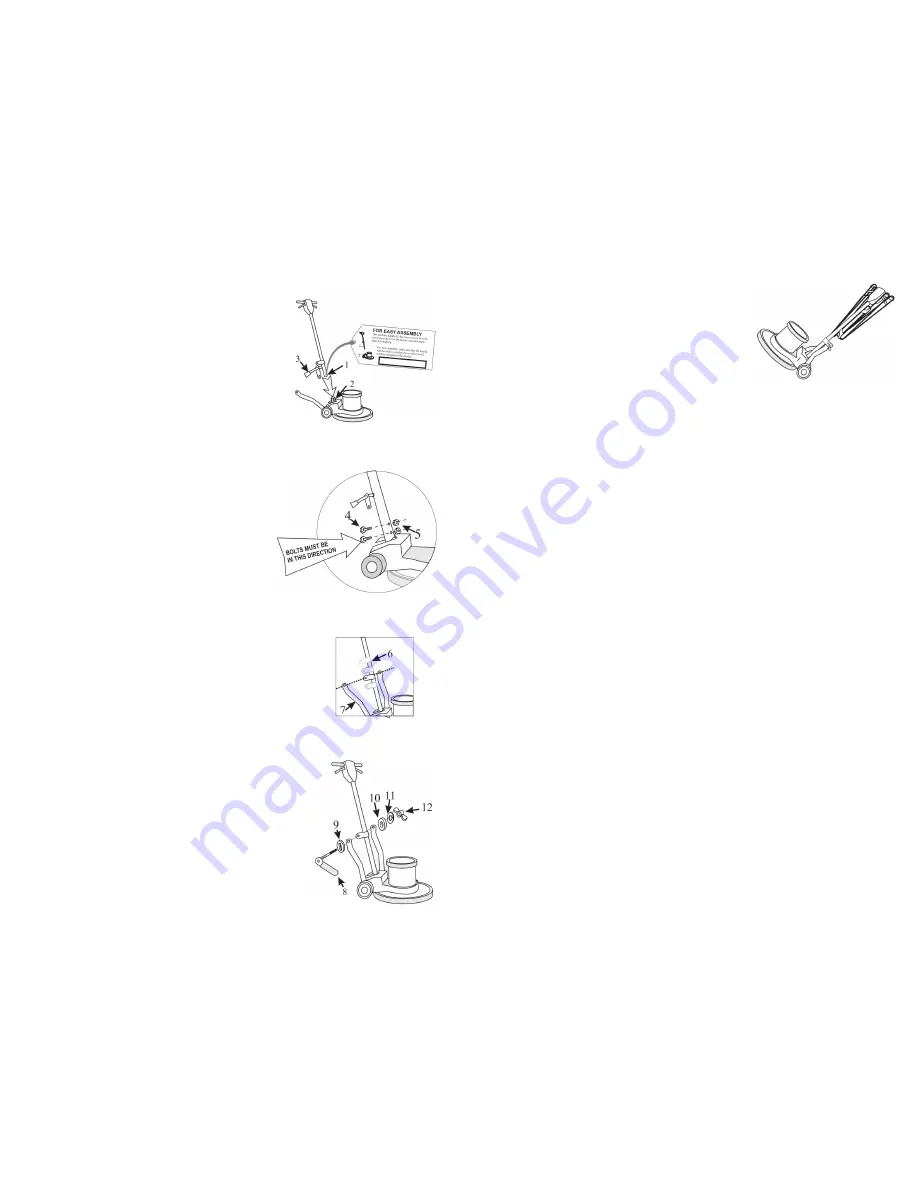
2.0 Install the Handle
This machine handle (1) has been custom fit to its
mounting yoke (2) at the factory and then taken apart
for shipping. For easy assembly, make sure that the
handle number on the tag (see right) matched the serial
number stamped on the chassis.
You will need 7/16” wrenches to complete the
assembly:
1. Remove the handle and mounting hardware from
the carton. Bolts, nuts, washers and the locking
lever assembly are in the plastic bag attached to
the handle.
2. Position the handle (1) over the mounting yoke
(2) with the power cord (3) facing away from the
motor. Push the tube down until the bolt holes are
lined up.
3. Insert the mounting bolts (4) into the bolt holes
from the back of the machine. Secure each bolt
with a locking nut (5). The locking nuts will face
the motor.
4. The handle mounting collar (6) is designed to
slide freely up and down the handle tube. This
feature allows the handle to be adjusted for the
comfortable operation of all users. Align the
mounting collar (6) and the two bent handle braces
(7).
5. Remove the lever assembly parts from the plastic
bag.
• Place the thick spacer with a rectangular hole
(9) onto the locking lever shaft (8). The spacer
must fit onto the rectangular neck of the lever.
• Insert the shaft through the mounting hole in
the right handle brace, the mounting collar and
the left handle brace.
• Place the spacer (10) on the shaft.
• Place the split washer (11) on the shaft.
• Adjust the wing nut for tightness. When
correctly installed, the collar slides easily when
the cam-engineered locking lever is “up,” but is
firmly fixed when the lever is “down.”