


Chapter – VI
R C p r e p a r a t i o n
( Servos )
At first the metal protective sleeves for the screws are pushed through the damping rubbers of the swash plate servos from
below and of the tail rotor servo from above.
Attention!
When using the tail rotor servo make sure that a possible stiffening rib on the upper side is flattened such that it
does not protrude from the rubber dampings. The reason for this is that this side of the tail rotor servo later is mounted to the
attachment blocks.
In addition, it is recommended to shorten the cable of the tail rotor servo which is much too long to a suitable length of 70mm
from the servo housing to the end of the plug. In order to do so, cut the Futaba BLS 251 cable at a distance of 30mm to the
housing and completely remove the black insulation. Also shorten the cable with the plug such that 30mm protrude from the
plug and re-solder the 3 strands (at first cover the single strands with a shrinking tube). Also from the plug the black insulation
has to be remove so that the cable is at flexible as possible.
Attention!
This procedure is necessary specially when using Mini V-Stabi or something similar if the sensors are includet in
one box with the rest of the electronic so that all the cables from the servos and receiver enter this box. If the cables are to
stiff or connected with cable ties they will transfere vibrations direct into the box which cause problems later during flight.
Look for further informations in Chapter XI for instance if you want to use a sattelite receiver.
Connect the swash servos directly to a free receiver channel (but not to the carb. or the pitch channel. Switch on the
transmitter. Neutralise all trim and sub-trim settings and all programmable mixers should be deactivated so that there is a
neutral pulse at the receiver channel and the servo takes its centre position (this is not possible with the tail servo).
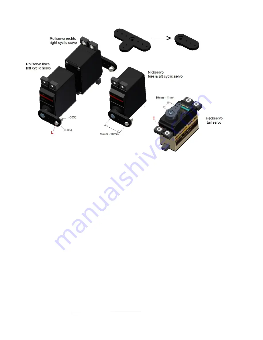
The installation has to be switched on when attaching the single servo arms to the multiple teeth shaft of the servo, so that it
is positioned at right angles to the housing. Please note the different alignment of the single servos in the image. It is
recommended to position the servos according to the drawings and mark them to avoid mistakes during the assembly in the
chassis.
If you have chosen the Futaba BLS 451 Servo recommended by me, I strongly recommend to use the enclosed thick 3mm
servo arms. These arms are sufficiently stiff and the servo gear remains undamaged during a crash. When using aluminium
arms the gear is nearly always defective.
The uneven number of teeth of the multiple teeth unit leads to a slightly different position during the rotation of the servo arm
by 180 degrees. That is how you can improve the rectangularity, if it was not optimal at the first positioning.
Try to find a positioning as good as possible and remove the unnecessary arms of the servo arm. Smooth the edges (this
works best on a sanding machine) as shown in the drawing above.
(Bag 6-
I
)
Attach the threaded link balls 0638 according to the drawing to the three swash plate servos from the lower side of
the arm and secure them on the upper side of the arm using the nuts 0638 (use Loctite).
The distance should be between 16mm and 18mm from the centre of rotation. The Futaba arms have an optimal value of
17.5mm.
For the tail rotor servo you have to use a normal 2mm plastic arm with a 1.5mm hole. The reasons for it is that a metal clevis
is provided which may never be used with an aluminium or carbon arm, because it is directly mounted into the 1.5mm hole.
The optimal mounting point is at 10mm – 11mm from the centre of rotation of the servo. This relatively low distance is
necessary because the transmission ratio at the tail drive is 1:1 in contrast to the one of most of the helicopters. Thus at the
front servo a smaller way is sufficient.
19


