background image

Operating Instructions

The unit must be properly operated and properly
maintained to help avoid accidents that could
damage the unit and injure the operator or
bystanders. This section of the Operating
Instructions manual review basic operations and
use of controls. These instructions should be
reviewed with all employees before they are
allowed to work with the machine. Keep these
instructions near the machine for easy reference.

Bead Loosening and Demounting

This machine may
operate differently
from machines you

have previously operated. Practice with a regular
steel wheel and tire combination to familiarize
yourself with the machine's operation and
function.

NOTE: Always review nicks and scratches with
owners of expensive wheel and tire combinations
prior to servicing.

IMPORTANT: Refer to the Performance Wheels
and Tires section of this manual before servicing
custom and performance wheel and tire
combinations.

IMPORTANT: Refer to the Tube Type Tires section
of this manual before servicing tires with tubes.
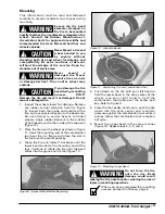
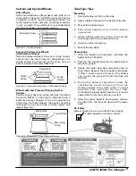
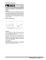
1.

Determine the correct side of the wheel for tire
removal. Remove the tire from the narrow side
(tire mounting side). Tire will not mount or
demount from the long side.

NOTE: On some wheels, the sides may be nearly
equal. Measure carefully. Only the narrow side is
used for mounting and demounting.

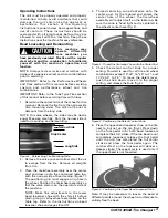
Figure 1 - Determining Tire Mounting Side

2.

Remove the valve core and allow all of the air
to escape from the tire. Remove all weights
from rim.

3.

Place the tire/wheel assembly over the center
post and down onto the contoured table top,
with the narrow side of bead seatup (figure 1).
The positioning pin must engage a lug hole in
the wheel. Position the tire/wheel assembly so
that the valve stem is on the operator’s side of
the machine.

NOTE: Make fine adjustments to the lower
bead loosener shoe with the shim kit before
placing mag or alloy wheel assemblies on the
table top. Refer to the instructions on bead
loosener shoe and pages 8 and 12.
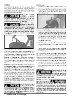
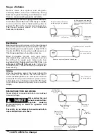
4.

Thread centering cone clockwise onto the
center post. As the tapered end enters the
center hole of the wheel, the tire/wheel
assembly will adjust itself on the table top. Be
sure the cone is hand tight and is centered in
the wheel’s center hole (Fig. 2).

Figure 2 - Thread the Centering Cone onto the Center Post
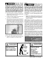
5.

Check the detent control knob for proper
setting. Forward is used for all tire and wheel
combinations except 15”x4”, 16”x5” to 7”, and
17.5”x5.5” to 7.5”. To move the detent lever,
push the knob down, move it to the proper
setting, and release the knob (fig.3).

Figure 3 - Positioning the Detent Control Knob
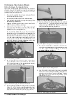
6.

Place the upper bead loosener shoe on the tire
next to, but not on, the rim (fig.4). Press down
on the foot pedal until both bead looseners
complete their full stroke. If the top bead is not
completely loosened, release the foot pedal
until the unit has completed the full return
stroke and press the foot pedal again. The
ratchet effect on the loosener will deliver a
deeper stroke. The repeat cycle is used only if
the upper bead is not loosened.

Figure 4 - Positioning the Upper Bead Loosener Shoe

Note: If may be necessary to loosen the bead at
different points around the wheel circumference to
entirely free the bead.

COATS 4050A Tire Changer • 3

CAUTION

!

Narrow Side 

Long Side 

Drop Center

Содержание Coats 4050A

Страница 1: ...s Revision 02 97 Safety Instructions Operating Instructions Installation Instructions Maintenance Instructions READ these instructions before placing unit in service KEEP these and other materials del...

Страница 2: ...to help prevent injury in typical shop activities Eye protection is essential during tire service activity Safety glasses with side shields goggles or face shields are acceptable Back belts provide su...

Страница 3: ...ation conforms to all applicable Local State and Federal Codes Rules and Regulations such as State and Federal OSHA Regulations and Electrical Codes Carefully check the unit for correct initial functi...

Страница 4: ...and with all parts orders Combination Tool Used in mounting and demounting operations Foot Pedal Operates the air valve for power bead loosening mounting and demounting Do It Now Now is a good time to...

Страница 5: ...o the contoured table top with the narrow side of bead seatup figure 1 The positioning pin must engage a lug hole in the wheel Position the tire wheel assembly so that the valve stem is on the operato...

Страница 6: ...lps in demounting tougher tires Figure 8 Removing Upper Bead 10 To remove the lower bead from the wheel repeat steps 8 9 and 10 REMEMBER Refer to the Tube Type Tire section of this manual before servi...

Страница 7: ...ads and to the inside of the top bead figure 10 2 Place the tire over the wheel as shown in figure 11 Hook the mounting end of the combination tool over the rim flange and place the slot in the tool o...

Страница 8: ...nd wheel positioned on the tabletop Dirt and debris could be blown into the air with enough force to injure the operator or bystanders Do not use the position to inflate a tire Bead Sealing 1 Connect...

Страница 9: ...tly to avoid over inflation Excessive pressure can cause tires to explode causing serious injury or death to operator or bystander REMEMBER If you removed the valve core for bead sealing it must be re...

Страница 10: ...lower shoe Figure 17 Installing 1 4 Shim 2 To service wheels over 11 wide extend the upper bead loosener post Remove the clevis pin raise the post to the appropriate height and reinsert the pin figur...

Страница 11: ...ng or forcing the tube 2 Apply rubber lubricant to the beads of the tire 3 Mount the bottom bead 4 Put a small amount of air into the tube to round it out 5 Apply rubber lubricant to the tube and the...

Страница 12: ...seated the tire is inflated Do not inflate the tire above the manufacturer s recommended pressure as stamped on the tire sidewall The typical inflation pressure for automobile tires is between 24 and...

Страница 13: ...removing 4 self tapping bolts and 3 self tapping screws 2 Depress and hold the foot pedal to extend the cylinder to the top of its stroke 3 Remove the plastic breather plug Fill the cylinder to withi...

Страница 14: ...chine on a regular basis C Clean the gauge lens frequently with glass cleaner D Make sure all fasteners are tightened securely E Make certain that all guards and covers are in place F Check for worn d...

Страница 15: ...e lathe chips etc Avoid areas where bystanders and customers may be present Workspace Requirements Air Source The unit requires a 5 CFM air source at 150 PSI The safe operating pressure range is betwe...

Страница 16: ...ny tire on a rim inspect the rim for rust tough spots bent edges or cracks that could prevent the tire from seating right If you spot any of these problems don t mount the tire until the rim has been...

Отзывы: