


2 •
Important: Always read and follow the information box instructions.
Balancing Your First Tire
1.
Turn the machine OFF then ON
(resets machine).
Note:
The machine wakes up using standard
clip-on wheel weight locations (Clip 1 & Clip 2)
and wheel dimensions.
2.
Mount a tire/wheel on the
balancer that will use standard
clip-on wheel weights.
Use the most appropriate mounting method.
3.
Always remove any weights
already attached to the wheel.
4.
Enter A & D wheel dimensions
using offset arm.
For Automatic Measurement — pull offset arm
out to the wheel, hold it still at clip-on weight
position against wheel flange, and wait for
BEEP. Return arm to home position.
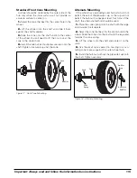
Clip-on Weight Location — viewed on a cut-
away rim for clarification.
Figure 1 - Clip-On Weight Location
Note A & D dimension values in information
box.
5.
Enter Width wheel dimension.
Use the plastic calipers to measure wheel
width. Press the W key. Use the keypad to enter
the Width value (between 2.0 and 20.0 inches).
Note W dimension value in information box.
6.
Lower the hood; wheel spins
and unbalances are measured
and displayed.
The corrective weight amount appears in control
panel weight display window for left and right
planes of the wheel.
7.
Raise hood after tire stops
rotating.
Note:
Wait for wheel to stop before raising the
hood.
8.
Rotate wheel until left plane
center bar blinks.
9.
Attach left plane corrective
weight.
Attach specified weight amount at top-dead-cen-
ter on inside flange of wheel.
10.
Rotate wheel until right plane
center bar blinks.
11.
Attach the right plane corrective
weight.
Attach specified weight amount at top-dead-cen-
ter on outside flange of wheel.
12.
Lower the hood to respin the
tire/wheel and check balance.
Your weight readings should now be 0.00.
Note:
Throughout this manual tire dimensions
are referred to as A, W, and D, see figure 2.
Figure 2 - A, W, and D Tire Dimensions


