8114307 03 06/06
© Copyright 2005 Hennessy Industries and COATS
All Rights Reserved
Printed in USA
Страница 1: ...Equipment and Tools Revision 06 06 READ these instructions before placing unit in service KEEP these and other materials delivered with the unit in a binder near the machine for ease of reference by...
Страница 2: ...qual to or more than that of the equip ment should be used Cords rated for less current than the equipment may overheat Care should be taken to arrange the cord so that it will not be tripped over or...
Страница 3: ...fe operating practices Always wear durable work clothing during tire service activity Loose fitting clothing should be avoided Tight fitting leather gloves are recommended to protect operator s hands...
Страница 4: ...on tact Hennessy Industries Inc 1601 J P Hennessy Drive LaVergne TN 37086 3565 615 641 7533 or 800 688 6359 www ammcoats com The motor unit of this machine contains a Class IIIa laser with a maximum o...
Страница 5: ...peration System 7 Setting Wheel Dimensions DIM 8 Definition of Dimensions DIM 8 Basic Wheel Data Entry 8 Entering Wheel Dimensions Manually 8 Control Panel Function and Review 9 11 Control Panel Quick...
Страница 6: ...n Use the plastic calipers to measure wheel width Press the W key Use the keypad to enter the Width value between 2 0 and 20 0 inches Note W dimension value in information box 6 Lower the hood wheel s...
Страница 7: ...tion of all controls Prevent accidents and injuries by ensuring the unit is properly installed operated and maintained Important Always read and follow the information box instructions 3 Do It Now Now...
Страница 8: ...enter A D measurements auto matically Pull offset arm out and up against the wheel flange hold it still at the clip on weight location figure 5B against the wheel flange and wait for the BEEP Figure...
Страница 9: ...idden Weight Location Viewed on a Cut Away Rim for Clarification Note The A2 and D2 dimensions are only required when the T2 Tape Direct Select Weight position is selected Figure 6B T2 Tape Hidden Tap...
Страница 10: ...ion is selected Figure 8B T2 Tape Hidden Tape A Weight Data Entry Diagram When using the Laser Guided Operation feature enter the wheel measurements by grasping the offset arm at the line laser and pu...
Страница 11: ...ates and blinks 3 Rotate the laser locator knob to position the laser locator dot at the desired weight location See figures 8A 8B Note For best performance choose a weight posi tion in the right plan...
Страница 12: ...width 5 Enter caliper measurement into W on balancer 6 Lower hood and spin wheel Entering Wheel Dimensions Manually Note To manually enter the A2 offset press SHIFT A To manually enter the D2 offset p...
Страница 13: ...d Shift and press 9 Then on the Wheel Cross section diagram the activated weight location LED illuminates the laser LED illuminates the Laser Guided Operation mode activates additonal balance modes ma...
Страница 14: ...Locator special blinking bars appear on either side of the cen ter bar to indicate the correct weight placement posi tion right plane Mode LED Indicators The mode s LED will illuminate to indicate th...
Страница 15: ...details Spoke 1 Spoke 2 toggle to set the Spoke 1 location and the Spoke 2 location for adhesive weights hidden weights Keypad Group The operator enters wheel data information selects functions and s...
Страница 16: ...ight loca tion is selected the balancer activates its Laser Guided Operation feature see page 7 Static Modes Choose a static balance for wheel assemblies that are not possible to balance dynamically o...
Страница 17: ...c patch weight bal ance when there is a very large unbalance in a tire assembly or if a very large tire has a large unbalance A weighted balance pad patch weight is placed inside the tire in the cente...
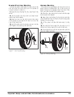
Страница 18: ...firmly against the shaft faceplate and that the hub nut engages the threaded shaft for at least four complete turns To assist in centering the wheel properly rotate the wheel and the shaft while tight...
Страница 19: ...17 Front Cone Mounting Alternate Mounting If the wheel has a protruding outer hub which will not permit the use of the pressure cup or the cup will not permit the hub nut to engage at least four turn...
Страница 20: ...Balance involves the loosening of tire beads and the inflation of a tire Training is necessary in tire changer opera tion and understanding the dangers involved during bead seating and tire infla tion...
Страница 21: ...nit operating properly 1 Keep the display clean and clear Use a damp cloth Do not use cleaners or solvents which leave oily or filmy residues behind 2 Keep the adapters cones faceplate threaded shaft...
Страница 22: ...opriate adapter to mount the wheel to the bal ancer Balance the wheel with the wheel cover or trim ring attached to the wheel Incorrectly mounted wheel Remount correctly Damaged wheel bolt holes Repla...
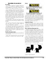
Страница 23: ...all the proper receptacles in accordance with state and local codes Setup Do not use the control panel control panel base accessory storage faceplate hood or shaft to lift the balancer Do not attempt...
Страница 24: ...eatures Automatic Data Entry for Offset and Diameter Manual Entry Backup on all Parameters Static on Screen Four Fixed Function Keys Seven Program Keys for user Friendly Operation Balancing Modes Dyna...
Страница 25: ...mm 8114339 40mm Small Cone Medium Cone Large Cone LightTruck Back Cone Rim Width Calipers Wheel Weight Pliers Hubnut Small Pressure Cup Rubber Lip Cone Spring Stub Shaft Extended Kit 8114337 28mm 8114...
Страница 26: ...22 Important Always read and follow the information box instructions...
Страница 27: ...Important Always read and follow the information box instructions 23...
Страница 28: ...8114307 03 06 06 Copyright 2005 Hennessy Industries and COATS All Rights Reserved Printed in USA...