background image

Safety

Operator Protective

Equipment

Personal protective equipment helps make tire serv-

icing  safer.  However,  equipment  does  not  take  the

place of safe operating practices. Always wear durable

work clothing during tire service activity. Loose fitting

clothing should be avoided. Tight fitting leather gloves

are  recommended  to  protect  operator’s  hands  when

handling  worn  tires  and  wheels.  Sturdy  leather  work

shoes with steel toes and oil resistant soles should be

used by tire service personnel to help prevent injury in

typical shop activities. Eye protection is essential dur-

ing  tire  service  activity.  Safety  glasses  with  side

shields, goggles, or face shields are acceptable. Back

belts  provide  support  during  lifting  activities  and  are

also  helpful  in  providing  operator  protection.

Consideration should also be given to the use of hear-

ing protection if tire service activity is performed in an

enclosed area, or if noise levels are high.

Failure to follow danger, warning, and cau-
tion  instructions  may  lead  to  serious  per-
sonal  injury  or  death  to  operator  or
bystander  or  damage  to  property.  Do  not
operate  this  machine  until  you  read  and
understand  all  the  dangers,  warnings  and
cautions  in  this  manual.  For  additional
copies  of  either,  or  further  information,
contact:

Hennessy Industries, Inc.

1601 J.P. Hennessy Drive

LaVergne, TN  37086-3565

(615) 641-7533 or (800) 688-6359

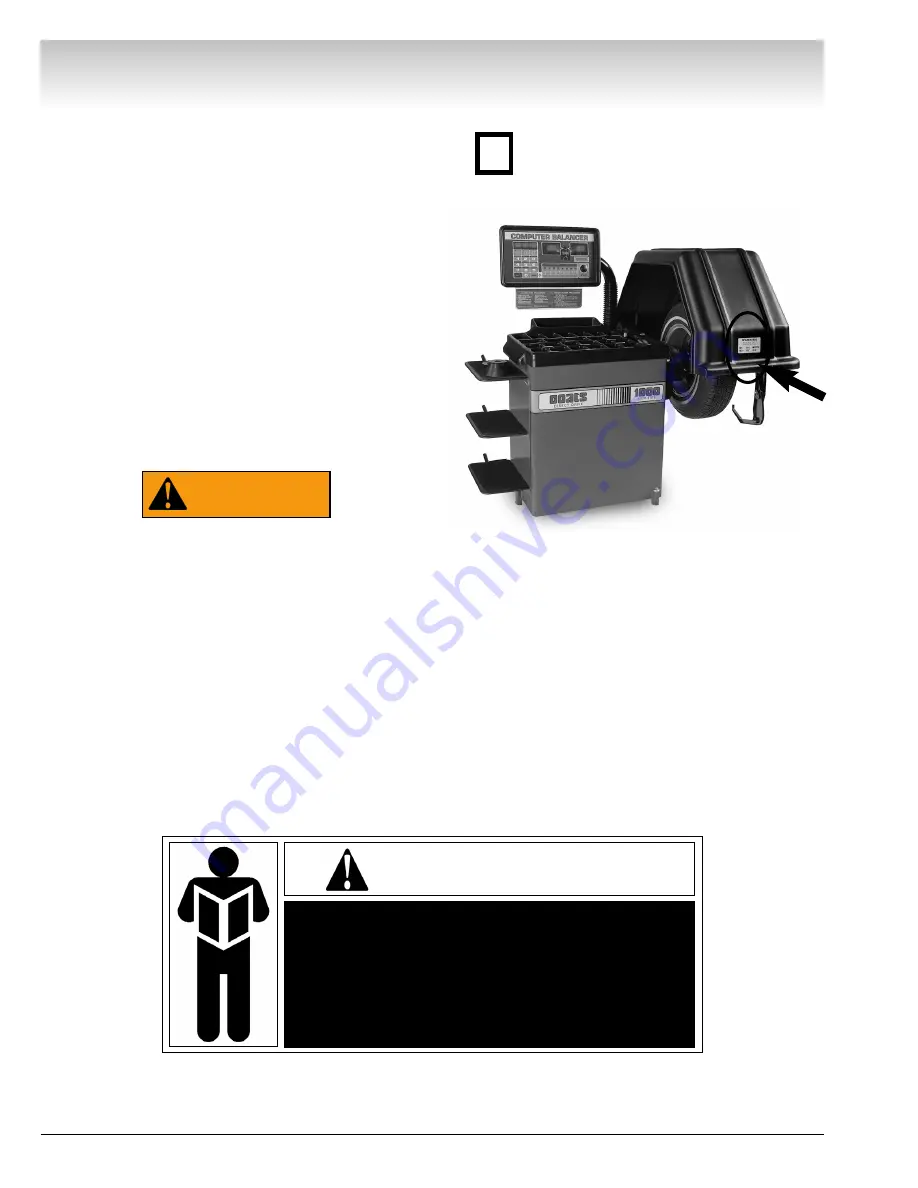
WARNING

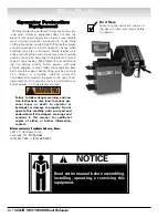
Do it Now

Make sure the instruction and warn-

ing decal is clean and clearly visible

to operator.

NOTICE

Read entire manual before assembling,

installing, operating, or servicing this

equipment.

iv • COATS 1000/1000D Wheel Balancer

Содержание coats 1000

Страница 1: ...otive Service Equipment and Tools Revision 11 05 1000 1000D Solid State WHEEL BALANCER Installation Instructions Operating Instructions Safety Instructions Maintenance Instructions READ these instructions before placing unit in service KEEP these and other materials delivered with the unit in a binder near the machine for ease of reference by supervisors and operators ...

Страница 2: ...ii COATS 1000 1000D Wheel Balancer Direct Drive ...
Страница 3: ...te Mounting 9 Optional Combi Adapter Mounting 9 Wheel Data Entry Wheel Offset A 10 Wheel Width W 10 Wheel Diameter D 10 Selecting Balancing Mode Dynamic Balancing 11 RV Balancing 11 Alloy 1 11 Alloy 2 11 Alloy 3 11 Alloy 4 11 Static 11 Match Mount 11 Selecting Balancing Options Hood Start 12 Round Off 12 Ounce Gram 12 Operator A B 12 Clear 12 Blank Rim 12 Reading the Displays Weight Displays 12 We...

Страница 4: ...rt during lifting activities and are also helpful in providing operator protection Consideration should also be given to the use of hear ing protection if tire service activity is performed in an enclosed area or if noise levels are high Failure to follow danger warning and cau tion instructions may lead to serious per sonal injury or death to operator or bystander or damage to property Do not ope...

Страница 5: ...refully inspect the unit on a regular basis and perform all maintenance as required Service and maintain the unit only with authorized or approved replacement parts Keep all instructions permanently with the unit and all decals labels notices on the unit clean and visible Do not override safety features Definitions of Hazard Levels Identify the hazard levels used in this manual with the following ...

Страница 6: ... a current rating equal to or more than that of the equipment should be used Cords rated for less current than the equipment may overheat Care should be taken to arrange the cord so that it will not be tripped over or pulled 9 Keep guards and safety features in place and in working order 10 Wear proper clothing Safety toe non slip footwear and protective hair covering to contain hair is recommende...

Страница 7: ...ents The balancer requires a 220 VAC 60Hz three phase power supply with 20 amp fuse or circuit breaker or a 220 VAC 60 Hz single phase power supply with 20 amp fuse or circuit breaker The three phase balancer is equipped with an approved cord and a 4 prong grounding plug to fit a Hubbell 2420 or Bryant 71520 grounding receptacle not included The single phase balancer is equipped with an approved c...

Страница 8: ...d Setup the Unit 1 Remove the carton from the pallet 2 Remove the shipping bolts in the three support feet 3 Cut the strap holding the hood in shipping position Do not use the control pod control pod arm face plate hood or stub shaft to lift the balancer Use help to remove the balancer from the pallet The unit is heavy and the weight is not evenly distrib uted Dropping the unit may cause personal ...

Страница 9: ...s pushed clear If not use a small screwdriver to push it in and out of the way 11 Slide the other flanged bearing into position followed by the washer retainer and cap plug figure 2 12 Raise the hood all the way and verify that the hood stop bracket on the side of the hood contacts the rubber hood stop solidly Lower the hood and verify that the other end of the hood stop bracket contacts the rubbe...

Страница 10: ... control pod If there is not enough room between the pod and the balancer weight tray to fully lower the instruction card the pod should be raised 22 Position the balancer in its final operating location Lightly tighten the four 5 16 nuts 23 Install the wheel caliper hook on the outside of the hood away from the balancer Remove the 1 4 screw towards the rear of the hood position the caliper hook o...

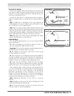
Страница 11: ...e left on all day 2 The displays will show zeros when the unit is first turned on Press any key to continue 3 Verify that the fan is running by placing your hand between the arbor faceplate and the motor housing You should feel air coming out from around the motor housing Do not operate the balancer if airflow is not present when the balancer is on 4 Lower the hood and press START The arbor facepl...

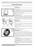
Страница 12: ...ment when the com puter BEEPS The diameter measurement tells the computer how far from the center of the hub the weights will be applied The offset and diameter measurement principles are the same for the 1000 however the operator must enter the measure ments instructions on page 8 When the wheel width is entered into the computer it is auto matically added to the offset measurement to determine t...

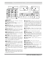
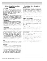
Страница 13: ...e display back on Round Off Toggles the balancer between the high accuracy mode 0 01 ounce increments and the normal mode 0 25 ounce increments Press and hold the SHIFT key and press 6 Operator A B Toggles the balancer between two operator memories Allows the balancer to be used by a second operator without clearing the meas urements or data stored by the first operator All measurements and prefer...

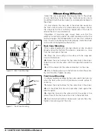
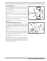
Страница 14: ... side of the hub 1 Place the cone spring on the arbor with the large end towards the balancer 2 Select the cone that best fits the center hole in the wheel Slide the cone onto the arbor with the large end towards the spring 3 Lift the wheel onto the arbor and center it on the cone 4 Attach the pressure cup to the hub nut and spin the assem bly onto the arbor Tighten securely Front Cone Mounting A ...

Страница 15: ...cones This adapter allows the mounting of 3 4 5 6 8 or 10 lug wheels by installing 3 4 or 5 swivel plates on the adapter plate 1 Assemble the adapter according to the instructions pro vided 2 Attach the adapter to the wheel The lug nuts must properly seat in the lug holes and engage at least four full threads for a secure mounting Use the wrench provided with the adapter and never use air tools or...

Страница 16: ...e calipers wide enough to reach around the tire Close the calipers so both tips contact the rim flanges Read the rim width on the calipers 3 Enter the measurement using the keypad It is now shown in the display above the wheel width key Wheel Diameter D This is the diameter of the wheel at the weight location Automatic diameter entry reads to 3 decimal places internally and rounds to 0 10 inch val...

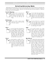
Страница 17: ...outer rim flange and hidden adhesive weights are not requested Attach the adhe sive weight to the horizontal plane on the outer edge of the wheel Static This mode balances the wheel assembly using only a single weight plane It does not compensate for side to side vibration as a dynamic bal ance would Use only one adhesive weight located as close to center as possible on the inside horizontal plane...

Страница 18: ...lay The balancer continues to use the measurement even though the display is blank This feature is typically utilized when the customer is with in view of the balancer and may become concerned by the measurement shown for the wheel diameter typical ly when metric or odd size wheel diameters are displayed Press and hold the SHIFT key and press 4 to blank the dis play Repeat the key sequence to reac...

Страница 19: ...fter applying the weights indicated by the balancer respin the wheel The displays should read 0 00 If the balancer indicates an additional weight should be applied in the same location as the first weight the first weight is too small Correct the first weight and respin If the balancer indicates an additional weight should be applied directly opposite the first weight the first weight is too big C...

Страница 20: ...e stem is at top dead center 10 Press 1 on the control panel 2 is now displayed in the weight display 11 Remove the wheel from the balancer Completely deflate the tire by removing the valve core After all the air pressure is exhausted follow the tire changer manufacturer s instruction for loosening the tire beads A second operator can use the balancer while the Match Mount operator does Steps 12 1...

Страница 21: ...Ds flash Mark the tire at top dead center 21 Remove the wheel from the balancer Completely deflate the tire by removing the valve core After all the air pressure is exhausted follow the tire changer manufacturer s instruction for loosening the tire beads A second operator can use the balancer while the Match Mount operator continues with Steps 22 23 and 24 Remember All data for the Match Mount pro...

Страница 22: ...ctures may not fit or function properly and may damage the balancer Calibration The balancer utilizes a self calibration scheme To keep your balancer in proper calibration this calibra tion procedure should be performed once a month or whenever the accuracy of the balancer is questioned 1 Mount a 14 15 or 16 inch diameter x 6 6 1 2 inch wide steel wheel assembly on the balancer It should be suitab...

Страница 23: ...d allow it to return to its stored position 7 Press MODE 8 Pull the distance gauge out and rotate it until it touches the inner edge of the rim flange Hold it there 9 Press the wheel offset key A and enter the dis tance measurement shown on the gauge 10 Press the wheel diameter key D and enter the diameter of the wheel as shown on the tire sidewall for example enter 140 for a 14 inch wheel The inn...

Страница 24: ...85009054 00 12 07 Copyright 2007 Hennessy Industries and COATS All Rights Reserved Printed in USA ...

Отзывы:

Похожие инструкции для coats 1000