background image

11 


5.2 Adjust the Level Sensor


  Notice: 

The level sensor is set in manufacturing and can be adjusted according to the type of 

product used, the size of the bottle, and orientation of the basket with spacers if 

required. If small bottles are used the supplied Bottle spacer disc can be placed in 

the base of the reservoir to raise the height of the bottle to reduce the residual 

adhesive in the bottle when low level is used. 


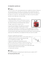
Before adjusting the Level Sensor  

1. Remove the plastic cap from the backside of reservoir.  

2. Connect the reservoir cord to the connector XS2 (8) on 

the reservoir as well as to socket XS2 on the controller. 

3. Empty a bottle of the product you use. 

4. Leave as much residue in the bottle as is required in 

order to prevent air getting into the product feed line.  

5. Insert the product bottle. For small bottles use the bottle holder. For 250ml 

product bottle, pay attention to ensure the bottle is aligned with the level sensor. 

6. Check that the product bottle inserted into the bottle holder is pressed against the 

level sensor. Only then the correct adjustment of the level sensor is possible.  


Procedure to Adjust the Level Sensor:  

           1. Switch on the power switch of the controller 97102, 97152 

            or RC15 to supply the reservoir with voltage 24 VDC. 

2. Turn controller power switch - 

“ON”. 


3. Remove the metal screw from the level sensor.  

4

. With an electrician’s screwdriver, find the point at which 

the sensor switches to the condition inactive. The LED is OFF”. 


5. Check this adjustment with a full bottle and an empty bottle again. 

6. Refit the metal screw to the level sensor. 

7. Put the plastic cap back.  


  Notice: 

The correct adjustment is exactly the point when the sensor switches “OFF”. 


Do not go beyond that point!


Содержание 2814023

Страница 1: ...1 EQ RC32 Automatic Reservoir SP IDH 2814023 Operating Manual...

Страница 2: ...ion 5 2 2 Control Panel Front Back of controller 6 3 Technical Data 7 4 Installation 8 4 1 Environmental and Operating Conditions 8 4 2 Connecting the Unit 8 4 3 Filling and Refilling the Product Rese...

Страница 3: ...are not observed the manufacturer can assume no responsibility Do not expose the connecting cable to heat oil or sharp edges Make sure the Unit stands stable and secure Use only original equipment re...

Страница 4: ...oint product level sensor for process controls Integrated solenoid vent valve 1 6 Field of Application Intended use The Loctite EQ RC32 Automatic Reservoir SP is equipped with a single point low level...

Страница 5: ...n connected to a controller 97102 97152 or RC15 the automatic reservoir is automatically pressurized when the controller is switched on and automatically depressurized when the controller is switched...

Страница 6: ...ressure ON OFF Switch 2 Tank Pressure Gauge 3 Valve Pressure Relief 4 Reservoir Feedline Fitting 5 Reservoir Locking Knob x 3 6 Reservoir Lid 7 Pneumatic Connection P in 8 Low Level connector XS2 9 Lo...

Страница 7: ...bs 4 8 8 Internal control voltages 24VDC Pneumatic Supply Clean dry air not to exceed 116 psi 8bar and filtered with a maximum of 10 micron Pneumatic hose size External dia 6mm Operating Temperature 1...

Страница 8: ...nt unnecessary loads on the fitting and to ensure compatibility Keep all fitting tight No direct sunlight no UV light No condensing humidity Avoid direct contact with water 4 2 Connecting the Unit Use...

Страница 9: ...d safety devices would become clogged and therefore ineffective Warning Before loosening the reservoir locking knobs 6 the EQ RC32 Automatic Reservoir must be depressurized pressure free When dispensi...

Страница 10: ...ighten the reservoir knobs by hand Set the depressurizing valve 1 to ON position pressurize On the controller 97102 switch the reservoir to active with the button On the controller 97152 or RC15 switc...

Страница 11: ...to the product feed line 5 Insert the product bottle For small bottles use the bottle holder For 250ml product bottle pay attention to ensure the bottle is aligned with the level sensor 6 Check that t...

Страница 12: ...pneumatic supply from the unit Clean the product hose and dispensing valve Recommended maximum idle times for different products are shown below Adhesive Maximum idle time for dispensing Systems Anaer...

Страница 13: ...spensing valve not correctly connected or defective Check the dispensing valve see instruction manual for dispensing valve Product reservoir pressure is too high Lower pressure longer dispensing time...

Страница 14: ...he feedline hose Remove the product bottle and insert a container with approx 0 5 liter of cleaning agent Put on the reservoir lid 6 and uniformly tighten the reservoir locking knobs 5 Operate the dis...

Страница 15: ...bing 360636 2 Tank Cord 2 m 147521 3 inch O D Black PE Teflon Lined feedline Tubing 33 feet length 142646 4 Reservoir Lid O ring 478505 5 Pressure Safety Relief Valve 360462 6 Anti Bubbler Kit 2 Adapt...

Страница 16: ...rishable items such as fuses filters lights etc No such claim shall be allowed in respect of products which have been neglected or improperly stored transported handled installed connected operated us...

Страница 17: ...T POSSIBLE UNDER APPLICABLE LAWS HENKEL EXPRESSLY DISCLAIMS ANY LIABILITY WHATSOEVER FOR ANY DAMAGES INCURRED DIRECTLY OR INDIRECTLY IN CONNECTION WITH THE SALE OR USE OF OR OTHERWISE IN CONNECTION WI...

Страница 18: ...Haw Par Technocentre SINGAPORE 149598 Henkel China Company Ltd No 928 Zhang Heng Road Zhangjiang Hi Tech Park Pudong Shanghai China 201203 Henkel Loctite Korea 8F Mapo Tower 418 Mapo dong Mapo gu Seou...

Отзывы: