4
Helvar 478 8-Subnet DALI Controller: Installation and User Guide
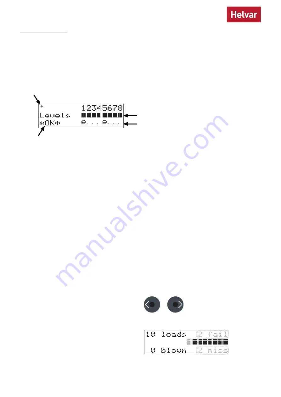
The Comms Indicator in the top left-hand corner of the main display screen indicates SDIM or DMX activity or DALI power/
activity:
•
For SDIM/DMX it is normally off, and flashes on intermittently to indicate SDIM or DMX activity.
•
If DALI power is on, then the Comms Indicator is on. It flashes to indicate DALI control activity.
The Overall Health Indicator in the bottom right corner shows whether there are faults in one or more channels:
•
If there are faults, it shows ‘Fault’ (and the Status LED flashes).
•
If there are no faults, it shows ‘OK’.
The main display screen appears:
•
When the 478 is powered on.
•
After 60 seconds of inactivity on the control panel .
•
After exiting the control panel options.
Comms Indicator (DALI, SDIM, DMX)
Overall Health Indicator
DALI channel numbers
Channel level indicators
Emergency devices
Configuration
We recommend configuring the 478 with Designer or Toolbox.
You can also use the LCD and the control panel buttons to adjust the DALI channel outputs directly, and configure options
for all and individual channels.
Note that the 478 is intended for controlling DALI ballasts, drivers and load interface units (except for the 490 Blinds
Controller). Do not connect controls to the DALI outputs (DALI channels 1–8), other than Helvar compatible sensors (see
‘Sensors’ on page 7), unless you selected Toolbox mode.
The following figure illustrates the main display screen on the LCD:
This section describes how to use the control panel buttons to adjust the DALI lighting level. During the process, the LCD
shows a status summary of all devices that are present on each of the channels that you select: first the nonemergency
devices, and then the emergency devices.
Adjust channel levels using the buttons
a. Adjust individual channels
From the main display screen, press the RIGHT button or
the LEFT button.
Channel 1 will flash, and the LCD will show the following
information about the nonemergency devices present on
this channel: how many devices there are (top left corner),
how many have failed (top right corner), how many lamps
are blown (bottom left corner) and how many devices are
missing (bottom right corner).
Use the control panel buttons to:
•
Set DALI channel levels
•
Navigate the system menus to adjust module settings


