Helvar
| Data is subject to change without notice.
www.helvar.com
i
Product description
The 478 is for controlling DALI ballasts, LED drivers, emergency devices and load interface units (except for the 490 Blinds
Controller). The flexible control inputs route an input address/group command, as a broadcast, to its corresponding DALI
channel output. The 478 operates in one of two modes to support the connection of controls:
•
Normal mode
: No device addressing is required. Helvar compatible presence sensors can be connected in addition to
DALI compatible control gear. The sensors provide local occupancy control for the DALI channels’ output to which they
are connected. Do not connect controls other than those listed (see ‘Sensors’ on page 7) to the DALI outputs (DALI
channels 1–8). This mode provides support for emergency devices only when using the DALI control input.
•
Toolbox mode
(Default): This allows a DALI output channel to act as a power supply, so that any DALI compatible
control gear or Helvar DIGIDIM controls can be connected. No automatic addressing takes place, so all the devices
connected on the DALI output channel must be programmed using Helvar’s Toolbox software. Output levels received
on the control inputs are broadcast on the corresponding output channel to provide local override. The ‘Toolbox mode’
option is available from the control panel. For more information, see ‘Set Toolbox mode’ on page 10.
8-Subnet DALI Controller (478)
Installation and User Guide
DALI channels
The 478 can control up to 8 DALI channels, each of up to 64 devices (limited by current consumption).
Control inputs
The 478 can be controlled using DALI, SDIM or DMX, and an override input.
NOTE: DALI AND SDIM/DMX MUST NOT BE CONNECTED SIMULTANEOUSLY.
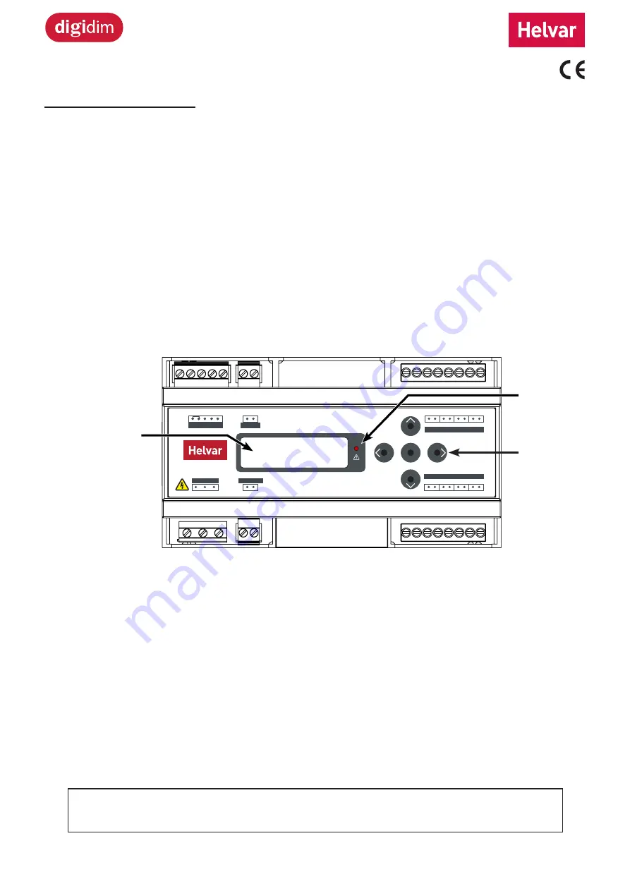
LCD display and control panel buttons
The front of the module has an LCD and five buttons to set basic configuration parameters and provide basic control of
channel levels.
Note
: The content of this manual refers to the operation of a 478 with firmware version 2.4 or later.
D5
D1
Ch1
Ch5
Ch2
Ch6
Ch3
Ch7
Ch4
Ch8
D6
D2
D7
D3
D8
D4
D-
D-
D-
D-
D-
D-
D-
D-
DALI CHANNELS
DALI CHANNELS
OK
A
0V
SC
B
TERM
S-DIM
S-DIM
S-DIM
0V OVR
OVERRIDE
N
L
N
E
(85 to 264)VAC
DA+ DA-
OVERRIDE
DALI SYSTEM
478 DALI Controller
SDIM/DMX
control
DALI channels 5–8
DALI channels 1–4
Mains supply
Override
input
DALI control
LCD
Control
Panel
Buttons
Status LED


