HELVAR Digidim 458 Скачать руководство пользователя страница 7

Digidim 458 Dimmer Installation Guide 


Helvar Ltd. 

Doc. No. 7860186 

Page 6 

Issue 1 (10/7/2008) 

4.2. 

Make Necessary Control Connections 
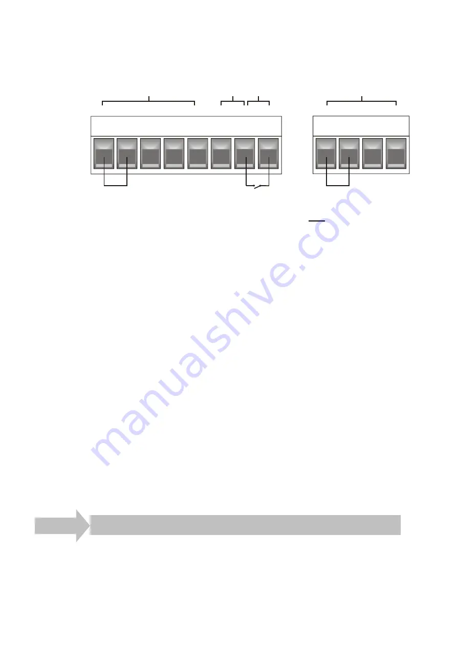
DALI

SDIM

Link for 

termination

Close for 

Override

Link for DALI 

power

SCN

0V

A

TERM

B

DA+

DA-

Touch

Panel Power

0V

-

/

OVR

+

Power 

Link

Override

+


The dimmer may be controlled by either DALI or S-DIM, but DO NOT CONNECT 
BOTH AT THE SAME THE TIME. 

Note: 

Use the cable sleeving (supplied) to provide an extra layer of insulation 
between the S-DIM, TouchPanel and Override low voltage signal wires and 
other wiring. 

S-DIM 

ƒ

  If connecting to an 

Imagine

 system, connect to the S-DIM terminals. 

If the dimmer is at the end of the S-DIM cable, wire between the ‘TERM’ and ‘B’ 
connections of the S-DIM terminals to enable the cable termination.  

TouchPanel 

You can supply one 

TouchPanel

 from the TouchPanel power connection terminal. 

Override 

If you wish to provide output level override functionality, wire between the ‘–/0V’ and 
‘OVR’ connections of the override input connection terminal. This sets the light output 
of all dimmer channels to the override level (the default is 100%, but can be changed).  

DALI 

ƒ

  If connecting to a 

Digidim

 system, use the DALI connector. 

If the built-in 250mA DALI power supply is required, wire between the ‘+’ and  
‘Power Link’ terminals of the DALI connector to provide DALI power. 
REMEMBER THAT YOU CANNOT EXCEED THE DALI POWER SUPPLY OF 250 mA. 

4.3. Check 

Connections 

Check that all the necessary connections have been made correctly and securely 

Step 5  Replace Cover & Power Up the Unit 

1.  Replace the cover using the original screws. (Screw size = M4x6). 
2.  Power up the dimmer unit by switching on the MCBs. 
3.  Check that the display screen lights up and the dimmer channel levels appear. 

Содержание Digidim 458

Страница 1: ...STEP STEP STEP STEP 5 5 5 5 Replace Cover Power Up Unit STEP STEP STEP STEP 4 4 4 4 Attach Module and Make Connections STEP 3 STEP 3 STEP 3 STEP 3 Electrical Installation STEP 2 STEP 2 STEP 2 STEP 2...

Страница 2: ...1 Open door and remove screws from inside door 1 2 Detach Dimmer Module and Remove Knockouts 1 Partially unscrew the two knobs 2 Remove the module from the chassis 3 Remove the knockouts Use the grom...

Страница 3: ...the area must be adequately ventilated Humidity must be within the range of 0 to 90 non condensing Do NOT install this product in a damp location 2 2 Mounting Procedure Use 4 screws not provided to m...

Страница 4: ...g WARNING THE SUPPLY INPUT MUST ONLY BE CONNECTED TO A SINGLE PHASE SUPPLY THE SUPPLY INPUT EARTH MUST BE CONNECTED Using Spring Lever Cage Clamp Terminals Note The supply earth supply neutral and out...

Страница 5: ...nd earth and neutral terminals as shown in the diagram below 3 2 Connect the Loads Connect the loads to the output terminals as shown below SUPPLY EARTH SUPPLY LIVE Miniature Circuit Breakers MCBs M A...

Страница 6: ...d Dimmer Channels 1 Remove the cables from the bypass terminals and connect them to the channel terminals Ensure that the terminal numbers correspond to the channels numbers 2 Connect the supply to th...

Страница 7: ...chPanel You can supply one TouchPanel from the TouchPanel power connection terminal Override If you wish to provide output level override functionality wire between the 0V and OVR connections of the o...

Страница 8: ...se address 1 At Set SDIM base press 2 Press or to select a base address and press to enter 3 Press to return to Addresses menu Note The base address is the first channel address from which the remaini...

Страница 9: ...no DALI or TouchPanel PSUs used Control board resettable fuse power devices thermal sensing Vertically mounted using four 4 5 mm mounting holes Weight Dimensions in mm Operating conditions Temperatur...

Страница 10: ...Helvar Ltd Hawley Mill Hawley Road Dartford Kent DA2 7SY UK Tel 44 1322 222 211 Fax 44 0 1322 282 216 www helvar com 8 Channel Dimmer Product 458 Doc No 7860186 Issue 1 Date 10 07 2008...

Отзывы: