36
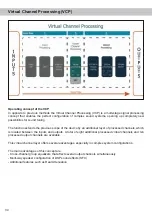
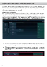
To configure the VCP, you first have to enable “Virtual Channel Processing” in the DCM menu of the DSP
PC-Tool software. Therefore, go to the “Virtual Channel Processing” tab in the DCM menu and click on the
right box with the VCP graphic. Then the configuration will be carried out in two steps. Here’s an example
of a 3-way configuration with a 2-way input signal.
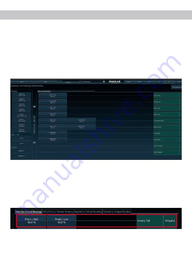
Workflow step 1 – Input routing
First, the input signals in the various input matrices (“Main to Virtual Routing”, “HEC / AUX to Virtual Rout
-
ing”, “Digital to Virtual Routing”) need to be routed to the respective virtual channels. This is the same as
in normal mode, means that the input signals on the left side are dragged and dropped onto the respective
summation matrix. The difference to normal mode is that the names and signal properties of the virtual
channels are defined here (Front L Full, Front R Full, Rear L Full, Rear R Full, Front Center Full etc.).
a.
First, all input signals must be applied to the respective designated signal types of the virtual channels,
means the input with the signal “front left” must be routed to the virtual channel “Front L Full” and so
forth.
b.
In the case of an adaptation of an OEM active multi-way system, all “front left” signals in this example
have to be summed up on the virtual channel “Front L Full” (the input EQ remains effective in the
inputs as usual).
Configuration of the Virtual Channel Processing (VCP)

