background image


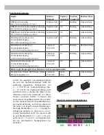
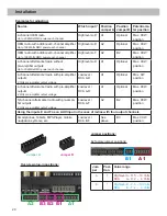
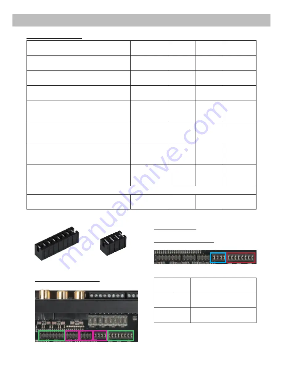
Overview plug-in positions:

Jumper positions:

Ex factory jumper positions:

Jum-

per

Posi-

tion

Value range

A

1

Highlevel A - D: 5 – 10 Volts 

RCA  

A - D: 2 –   4 Volts

B

1

Highlevel E - F: 5 – 10 Volts 

RCA  

E - F: 2 –   4 Volts 

Jumper A

Jumper B

A1

B1

A2

B3 B2

A1

B1

20

Examples for adjusting:

Source

Which input? Position 

Jumper A

Position 

Jumper B

Potentiome-

ter position

4-channel OEM radio

Up to 25 Watts RMS power each channel

Highlevel A-D

A1

Optional

Max. CCW 

position

OEM radio with additional 4-channel amplifier

Up to 100 Watts RMS power each channel

Highlevel A-D

A2

Optional

Max. CCW 

position

OEM radio with additional 6-channel amplifier

Up to 100 Watts RMS power each channel

Highlevel A-F

A2

B2

Max. CCW 

position

4-channel aftermarket radio without 

 pre-amplifier outputs

Up to 25 Watts RMS power each channel

Highlevel A-D

A1

Optional

Max. CCW 

position

4-channel aftermarket radio with  pre-amplifier 

outputs

2 Volts pre-amplifier output voltage

Lowlevel / 

RCA A-D

A1

Optional

Max. CW 

position

4-channel aftermarket radio with  pre-amplifier 

outputs

4 Volts pre-amplifier output voltage

Lowlevel / 

RCA A-D

A1

Optional

Max. CCW 

position

5/6-channel aftermarket radio with pre-ampli-

fier outputs

8 Volts pre-amplifier output voltage

Lowlevel / 

RCA A-F

A2

B2

Max. CCW 

position

Using the inputs E and F as an AUX input in the case of radios with four output channels

Smartphones, Tablets, MP3-Player, mobile 

navigation systems, etc.

Lowlevel / 

RCA E-F

See 

above

B3

Max.CCW 

position

Installation

Содержание P SIX DSP MK2

Страница 1: ...P SIX DSP MK2 6 Kanal Verstärker mit integriertem DSP 6 channel Amplifier with integrated DSP deutsch english ...

Страница 2: ...t muss der Verstärker professionell befestigt werden Dieses geschieht über Schrauben die in eine Montagefläche ein geschraubt werden die wiederum genügend Halt bieten muss Bevor Sie die Schrauben im Montagefeld befesti gen vergewissern Sie sich dass keine elektrischen Kabel und Komponenten hydraulische Bremslei tungen der Benzintank etc dahinter verborgen sind Diese könnten sonst beschädigt werden...

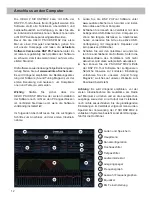
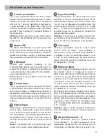
Страница 3: ...ei Verwendung des Line Output der Cinch Ausgänge genutzt werden Beide Anschlüs se sind intern parallel geschaltet 17 Output Channels E F Lautsprecherausgänge E und F für den An schluss von Lautsprechersystemen Diese Kanäle sind 2 Ohm stabil 9 10 11 12 13 14 15 16 17 1 4 3 2 5 6 7 8 1 Control Taster Dient zum Umschalten der Sound Setups oder zum Resetten des Gerätes 2 Status LED Die Status LED zeig...

Страница 4: ...ang im SPDIF Format für den An schluss an Signalquellen mit digitalem Ausgang Die Sampling Rate dieses Eingangs muss zwi schen 12 96 kHz liegen Das Eingangssignal wird automatisch an die interne Abtastrate angepasst Um diesen Eingang zu aktivieren und in der Laut stärke regeln zu können wird eine optional erhält liche Fernbedienung empfohlen Hinweis Es können ausschließlich Stereosignale und keine...

Страница 5: ... abgesenkt werden bis die LED erlischt 11 Fuse Sollten die Sicherungen im Inneren des Gerätes durch eine Fehlfunktion zerstört werden wird die ses durch das Aufleuchten der roten LED ange zeigt Bei normalem Betrieb leuchtet die LED grün 12 GND Das Massekabel sollte am zentralen Massepunkt dieser befindet sich dort wo der Minuspol der Bat terie zum Metallchassis des Kfz geerdet ist oder an einer bl...

Страница 6: ...ärker automatisch einschaltet sobald ein Lautsprechersignal anliegt 3 Einstellung der Eingangsempfindlichkeit Achtung Es ist zwingend notwendig die Ein gangsempfindlichkeit der P SIX DSP MK2 an die Signalquelle anzupassen um Schäden am Verstärker zu vermeiden Um die Eingangsempfindlichkeit zu verändern verwenden Sie zunächst die drei Drehpotentio meter Punkt 6 Seite 3 Input Sensitivity Die Einstel...

Страница 7: ...Welcher Eingang Position Jumper A Position Jumper B Position Potis OEM Radio 4 kanalig Bis 25 Watt Sinusleistung pro Kanal Highlevel A D A1 Beliebig Linksanschlag OEM Radio mit Zusatzverstärker 4 kanalig Bis 100 Watt Sinusleistung pro Kanal Highlevel A D A2 Beliebig Linksanschlag OEM Radio mit Zusatzverstärker 6 kanalig Bis 100 Watt Sinusleistung pro Kanal Highlevel A F A2 B2 Linksanschlag Handels...

Страница 8: ...e der Drehpotentiometer optimal an ihre Signalquel le anzupassen führen Sie bitte die folgenden Schritte durch 1 Schließen Sie während dieser Prozedur keine Lautsprecher an die Ausgänge des Verstärkers an und schalten Sie ggfs an geschlossene Verstärker ab 2 Drehen Sie die Lautstärke Ihres Radios auf 90 der Gesamtlautstärke und spielen Sie über das CD Laufwerk ein 1 kHz Testsignal Vollaussteuerung...

Страница 9: ...itt von mindestens 16 mm Bei längeren Leitungen empfehlen wir einen Quer schnitt von 25 mm bis 35 mm Das Massekabel gleicher Querschnitt wie das 12 V 24 V Kabel muss an einem blanken von Lackresten befreiten Massepunkt des Kfz Chassis oder direkt an dem Minuspol der Autobatterie angeschlossen werden 6 Anschluss des Remote Eingangs Der Remote Eingang REM muss mit dem Remote Ausgang des Radios verbu...

Страница 10: ...mals die Lautsprecher leitungen mit der Kfz Masse Fahrzeugkaros serie Dieses kann Ihren Verstärker und Ihre Lautsprecher zerstören Achten Sie darauf dass alle Lautsprechersy steme phasenrichtig angeschlossen sind d h Plus zu Plus und Minus zu Minus Vertauschen von Plus und Minus hat einen Totalverlust der Basswiedergabe zur Folge Der Pluspol ist bei den meisten Lautsprechern gekennzeichnet Die Imp...

Страница 11: ...uf www audiotec fischer com 2 Verbinden Sie die Stecker des Easy Plug Ka bels mit dem Autoradio 3 Verbinden Sie den Highlevel Stecker 8 poliger Stecker mit den jeweiligen Eingängen des Ver stärkers Der Stromversorgungsstecker 4 po liger Stecker bleibt ungenutzt Hinweis MOST Bus Bei einigen Fahrzeugen kann es notwendig sein die Lichtleiterverbindung aus dem Original Radio anschlussstecker auszulöse...

Страница 12: ...ngeschlossen ist Verbinden Sie diesen erst wenn die Software vollständig installiert ist Im folgenden Abschnitt lesen Sie die wichtigsten Schritte zum Anschluss und der ersten Inbetrieb nahme 1 Laden Sie die DSP PC Tool Software unter www audiotec fischer com herunter und instal lieren diese auf ihrem Computer 2 Schließen Sie danach den Verstärker mit dem beiliegenden USB Kabel an den Computer an ...

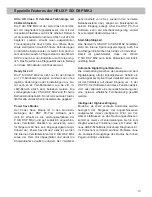
Страница 13: ...aktiv ist werden die internen Verstärkerstufen der P SIX DSP MK2 sowie der Rem Out abgeschaltet und damit die Stromaufnahme deutlich reduziert Der Verstärker geht innerhalb von 2 Sek wieder in den normalen Betriebszustand über sobald ein Musiksignal an seinem Eingang anliegt Über die DSP PC Tool Software kann die Abschaltverzögerung variiert bzw komplett deaktiviert werden Start Stopfähigkeit Das ...

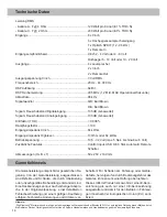
Страница 14: ...lot Automatic Remote Schalter Abmessungen H x B x T 50 x 250 x 190 mm Technische Daten Die Garantieleistung entspricht der gesetzlichen Re gelung Von der Garantieleistung ausgeschlossen sind Defekte und Schäden die durch Überlastung oder unsachgemäße Behandlung entstanden sind EineRücksendungkannnurnachvorherigerAbspra che in der Originalverpackung einer detaillierten Fehlerbeschreibung und einem ...

Страница 15: ... location to insure that there are no electrical cables or components hydraulic brake lines or any part of the fuel tank located behind the mounting surface Failure to do so may result in unpredictable damage to these components and possible costly repairs to the vehicle General instruction for connecting the HELIX P SIX DSP MK2 amplifier The HELIX P SIX DSP MK2 amplifier may only be installed in ...

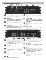
Страница 16: ...els A D Speaker outputs A D for connecting speaker systems The channels A and B may not be loaded with more than 4 Ohms all other channels are 2 Ohms stable 10 Clipping LED This LED lights up red if one of the analog inputs is overdriven 11 Fuse This LED lights up red if a fuse is faulty in the device 12 GND Connector for the ground cable negative terminal of the battery or metal body of the vehic...

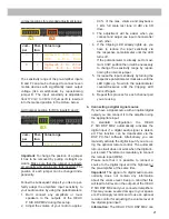
Страница 17: ...ream 6 Input Sensitivity These potentiometers are used to adjust the input sensitivity of the low and highlevel inputs for the individual stereo signals This is not a volume con trol it s only for adjusting the amplifier gain The control range of the RCA Line Input is 2 4 Volts and 5 10 Volts for the Highlevel Input The input sensitivity range can be changed by repositioning jumpers inside the dev...

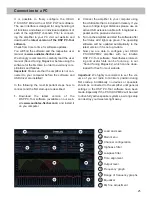
Страница 18: ...radio This is only activated if the head unit is switched on Thus the amplifier is switched on and off together with the head unit This input needn t to be assigned if the Highlevel Input is used To deactivate the automatic turn on function read the description on page 22 Configuration of the remote input 14 12 V 24 V The amplifier can be operated with 12 V or 24 V supply voltage Connect the power...

Страница 19: ...rket radio using appropriate ca bles loudspeaker cables with 1 mm AWG 18 max It is not mandatory to use all speaker inputs Make sure that the polarity is correct If one or more connections have reversed polarity it may affect the performance of the amplifier If this input is used the remote input REM does not need to be connected as the amplifier will automatically turn on once a loudspeaker signa...

Страница 20: ... Watts RMS power each channel Highlevel A F A2 B2 Max CCW position 4 channel aftermarket radio without pre amplifier outputs Up to 25 Watts RMS power each channel Highlevel A D A1 Optional Max CCW position 4 channel aftermarket radio with pre amplifier outputs 2 Volts pre amplifier output voltage Lowlevel RCA A D A1 Optional Max CW position 4 channel aftermarket radio with pre amplifier outputs 4 ...

Страница 21: ...tentiometer until the LED turns off If the potentiometer is already set to maxi mum CCW position then it will be necessary to change the sensitivity range by reposi tioning the internal jumper 5 Increase the input sensitivity by turning the respective potentiometer clockwise until the LED lights up Now turn the potentiometer counterclockwise until the Clipping LED turns off again 6 Repeat this pro...

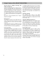
Страница 22: ...nnected as long as the car radio has BTL output stages 7 Configuration of the remote input The HELIX P SIX DSP MK2 will be turned on automatically if the highlevel inputs High level Input are used or if a signal is applied to the remote input REM The Automatic Remote switch allows to deactivate the automatic turn on feature The feature should be deactivated if there are e g disturbing noises while...

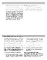
Страница 23: ...level plug 8 pole connector to the appropriate HELIX P SIX DSP MK2 input The power supply plug 4 pole connector re mains unused Note Cars equipped with MOST bus In cars equipped with MOST bus structure it is mandatory to unplug the fiber optic cable from the original radio connector and insert it into the ISO adaptor which has a dedicated recess for this 23 rectly to the wires of the loudspeakers ...

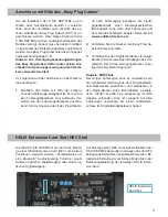
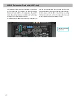
Страница 24: ...ming module an additional optical digi tal input or an optical digital output To install a HELIX Extension Card it is necessary to remove the bottom plate and one side panel of the P SIX DSP MK2 and replace it by the new side pan el that comes with the HEC Any further mounting information will be found in the instruction manual of the respective HELIX Extension Card HELIX Extension Card slot ...

Страница 25: ...most important steps how to connect and the first start up are described 1 Download the latest version of the DSP PC Tool software available on our web site www audiotec fischer com and install it on you computer 2 Connect the amplifier to your computer using the USB cable that is included in delivery If you have to bridge longer distances please use an active USB extension cable with integrated r...

Страница 26: ...g the car Once the Power Save Mode is active the remote output Rem Out and the inter nal amplifier stages will be turned off The HELIX P SIX DSP MK2 will reactivate the remote output and the internal amplifier stages within a second if a music signal is applied It is possible to either mod ify the turn off time of 60 sec or completely deacti vate the Power Save Mode via the DSP PC Tool software St...

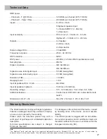
Страница 27: ... down to 6 Volts Additional features Control Input USB HEC slot Automatic Remote switch Dimensions H x W x D 50 x 250 x 190 mm 1 97 x 9 84 x 7 48 The limited warranty comply with legal regulations Failures or damages caused by overload or improp er use are not covered by the warranty Please return the defective product only with a valid proof of purchase and a detailed malfunction description Tech...

Страница 28: ...Audiotec Fischer GmbH Hünegräben 26 57392 Schmallenberg Germany Tel 49 2972 9788 0 Fax 49 2972 9788 88 E mail helix audiotec fischer com Internet www audiotec fischer com ...

Отзывы: