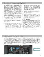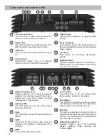
sure that the loudspeaker systems are correctly
connected (phase), i.e. plus to plus and minus to
minus. Exchanging plus and minus causes a total
loss of bass reproduction. The plus pole is indicated
on most speakers. The impedance of the speakers
of the channels A and B must not be lower than
4 Ohms. All other channels can be loaded with a
minimum of 2 Ohms. The speaker outputs are not
bridgeable.
10
Clipping LED
This LED lights up red if one of the six
Line Inputs
or
Highlevel Inputs
is overdriven. The LED has no
function if the device is fed with digital input signals.
If this LED lights up reduce the input sensitivity by
using the potentiometers until the LED goes out.
11
Fuse
If a severe malfunction inside the amplifier will blow
the internal fuses the LED lights up red. During nor-
mal operation this LED lights up green.
12
GND
The ground cable should be connected to a com-
mon ground reference point (this is located where
the negative terminal of the battery is grounded
to the metal body of the vehicle) or to a prepared
metal location on the vehicle chassis i.e. an area
which has been cleaned of all paint residues. Rec-
ommended cross section: min. 16 mm² / AWG 6.
13
REM
The remote input has to be used to turn on/off the
P SIX DSP MK2 if the signal source which is con-
nected to the highlevel inputs is not activating the
“automatic turn-on” function or if the amplifier shall
only be activated/deactivated by a remote signal
applied to the remote input (
REM
).
The remote lead should be connected to the remote
output / automatic antenna (aerial positive) output
of the head unit/car radio. This is only activated if
the head unit is switched on. Thus the amplifier is
switched on and off together with the head unit. This
input needn´t to be assigned if the
Highlevel Input
is used.
To deactivate the “automatic turn-on” function read
the description on page 22, “Configuration of the
remote input”.
14
+12 V / +24 V
The amplifier can be operated with +12 V or +24 V
supply voltage. Connect the power cable to the pos-
itive terminal of the battery. Recommended cross
section: min. 16 mm² / AWG 6.
15
Line Output
2-channel pre-amplifier output for connecting
external amplifiers. The output voltage is 3 Volts
max. The outputs can be assigned to any of the in-
puts as desired using the DSP PC-Tool software. If
you use this output it is mandatory to turn on/off the
external amplifier via the
Rem Out
in order to avoid
any pop noise.
16
Rem Out
We strongly recommend to use this output for turn-
ing on/off additional amplifiers that are connected
to the
Line Outputs
of the HELIX P SIX DSP MK2.
This is essential to avoid any interfering signals.
This output is activated automatically as soon as
the booting process of the DSP is completed. Ad-
ditionally this output will be turned off during the
“Power Save Mode” or a software update process.
17
Output Channels E - F
These connections serve as speaker outputs for the
channels E - F. Never connect the loudspeaker ca-
bles with the car chassis ground. It damages your
amplifier and your speakers. Ensure that the loud
-
speaker systems are correctly connected (phase),
i.e. plus to plus and minus to minus. Exchanging
plus and minus causes a total loss of bass repro-
duction. The plus pole is indicated on most speak-
ers. Output channels E and F can be loaded with a
minimum of 2 Ohms. The speaker outputs are not
bridgeable.
18
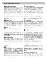
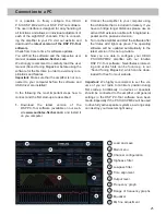
Initial start-up and functions

