14
Initial start-up and functions
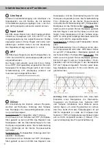
pair E/F from 15 to 4,000 Hz. The subsonic /high-
pass filter cuts off very low frequencies which are
not in the audible range and relives the amplifier
and the subwoofer. Additionally the amplifier will
have more power available for the audible frequen-
cies. This control is always activated and its adjust-
ment is mandatory.
7
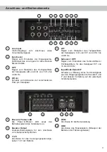
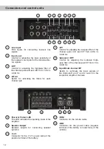
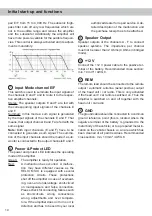
Input Mode channel E/F
This switch is used to summate the input signals of
the channels E and F and to route it to the respec-
tive amplifier channels.
Stereo: The speaker outputs E and F are fed with
the corresponding input signals of the channels E
and F.
Summed: In this mode a sum signal is generated
by the input signals of the channels E and F. That
means, that output channel E and F are fed with the
same signal.
Note:
Both input channels (E and F) have to be
connected to generate a sum signal. The summa-
tion of the input channels should be made if a sub-
woofer is connected to the output channels E and F.
8
Power & Protect LED
The power and protect LED indicates the operating
mode of the amplifier.
Green: The amplifier is ready for operation.
Red:
A malfunction has occurred. A malfunc-
tion may have different causes as the
HELIX M SIX is equipped with several
protection circuits. These protections
shut off the amplifier in case of overheat-
ing, over- and undervoltage, short-circuit
on loudspeakers and false connection.
Please check for connecting failures such
as short-circuits, wrong connections,
wrong adjustments and over tempera-
ture. If the amplifier does not turn on it is
defective and has to be sent to your local
authorized dealer for repair service. A de-
tailed description of the malfunction and
the purchase receipt has to be attached.
9
Speaker Output
Speaker outputs of the channels A - F to connect
speaker systems. The impedance per channel
must not be lower than 2 Ohms (4 Ohms in bridged
mode).
10
+12 V
Connect the +12 V power cable to the positive ter-
minal of the battery. Recommended cross section:
min. 10 mm² / AWG 8.
11
REM
The remote lead should be connected to the remote
output / automatic antenna (aerial positive) output
of the head unit / car radio. This is only activated
if the head unit / car radio is switched on. Thus the
amplifier is switched on and off together with the
head unit / car radio.
12
GND
The ground cable should be connected to a common
ground reference point (this is located where the
negative terminal of the battery is grounded to the
metal body of the vehicle) or to a prepared metal lo-
cation on the vehicle chassis i.e. an area which has
been cleaned of all paint residues. Recommended
cross section: min. 10 mm² / AWG 8.
Содержание M SIX
Страница 19: ...19 Notizen Notes ...

