background image

13

Initial start-up and functions

1

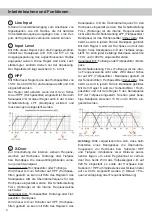
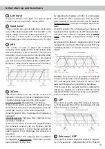
  Line Input

6-channel  lowlevel  line  input  to  connect  signal 

sourc es such as head units / radios / DSPs. 

2

  Input Level

These controls are used to adapt the input sensi-

tivity of the channel pairs A/B, C/D and E/F to the 

output voltage of the connected signal source. 

This is not a volume control, it´s only for adjusting 

the amplifier gain. The control range is 0.5 - 6 Volts.

3

 HPF

This  control  is  used  to  adjust  the  crossover 

 frequency of the highpass filter of the channel pairs 

A/B and C/D from 15 Hz to 4,000 Hz. This control is 

activated if the 

X-Over

 switch of the specific chan-

nel pair is set to HPF (highpass filter). On channel 

pair C/D it is also activated in switch position LPF / 

Bandpass, means that its adjustment is mandatory.

4

 X-Over

This switch allows to set the internal crossover to 

highpass, fullrange or lowpass / bandpass mode.  

The filter options depend on the channel pair.

Channel pair A/B: Highpass filter or fullrange.

If this 

X-Over

 switch is set to HPF (highpass filter) 

the crossover frequency for the highpass can be ad-

justed with control 3 of the channel pair A/B. 

At switch position FULL (fullrange) the crossover is 

bypassed.

Channel pair C/D: Highpass filter, fullrange or low-

pass filter / bandpass. 

If this 

X-Over

 switch is set to HPF (highpass filter) 

the  crossover  frequency  for  the  highpass  can  be 

adjusted with control 3 of the channel pair C/D. At 

switch  position  FULL  (fullrange)  the  crossover  is 

bypassed. 

At switch position LPF (lowpass filter / bandpass) 

the highpass is always active. That means a band-

pass is created in any case.

By adjusting the highpass (control 3) and lowpass 

filter (control 5 of the channel pair C/D) any band-

pass between 15 Hz and 4,000 Hz can be realized. 

Channel pair E/F: Fullrange or lowpass filter / band-

pass. 

At switch position FULL (fullrange) the crossover is 

bypassed. If this switch is set to LPF (lowpass filter / 

bandpass)  the  subsonic / highpass  filter  is  always 

active. That means a bandpass is created in any 

case.

By adjusting the subsonic / highpass (control 6) and 

lowpass filter (control 5 of the channel pair E/F) any 

bandpass between 15 Hz and 4,000 Hz can be re-

alized. 

Caution:

 To avoid a loss of gain make sure that the 

crossover frequencies of the highpass or subsonic / 

HPF and lowpass filters do have an interval of at 

least two octaves when generating a bandpass. 

That means if the lowpass signal is adjusted to 

320 Hz the highpass or subsonic / HPF should be 

adjusted to 80 Hz or less (one octave = doubled fre-

quency or halved frequency). 

5

 LPF

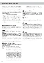
This control is used to adjust the crossover frequen-

cy of the lowpass filter of the channel pairs C/D and 

E/F from 40 Hz to 4,000 Hz. 

6

  Subsonic / HPF

This control is used to adjust the crossover frequen-

cy of the subsonic / highpass filter of the channel 

Содержание M SIX

Страница 1: ...deutsch english M SIX 6 Kanal Verstärker mit integrierter aktiver Frequenzweiche 6 channel amplifier with integrated active crossover ...

Страница 2: ...heit muss der Verstärker professionell befestigt werden Dieses geschieht über Schrauben die in eine Montagefläche ein geschraubt werden die wiederum genügend Halt bieten muss Bevor Sie die Schrauben im Montagefeld befesti gen vergewissern Sie sich dass keine elektrischen Kabel und Komponenten hydraulische Bremslei tungen der Benzintank etc dahinter verborgen sind Diese könnten sonst beschädigt wer...

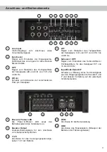
Страница 3: ...um Einstellen der Eingangsemp findlichkeit des Line Inputs für die einzelnen Stereo Kanäle 3 HPF Regler zum Einstellen des Hochpassfilters der Kanalpaare A B und C D von 15 Hz bis 4 000 Hz 4 X Over Schalter zum Aktivieren der verschiedenen Filter pro Kanalpaar 5 LPF Regler zum Einstellen des Tiefpassfilters der Kanalpaare C D und E F von 40 Hz bis 4 000 Hz 6 Subsonic HPF Regler zum Einstellen des ...

Страница 4: ...er Bandpass Wird dieser X Over Schalter auf HPF Hochpass filter gestellt so kann mit Hilfe des Reglers 3 des Kanalpaares C D die Übernahmefrequenz für den Hochpass eingestellt werden Bei Schalterstellung FULL Fullrange ist die interne Frequenzweiche nicht aktiv Bei Schalterstellung LPF Tiefpassfilter Bandpass ist das Hochpassfilter immer aktiv Das heißt es wird in jedem Fall ein Bandpass gebildet ...

Страница 5: ...D zeigt den Betriebszustand des Verstärkers an Grün Verstärker eingeschaltet und betriebsbereit Rot Es besteht eine Fehlfunktion des Verstär kers Diese Fehlfunktion kann unterschied liche Ursachen haben da die M SIX mit verschiedenen elektronischen Schutzschal tungen ausgestattet ist Diese schalten den Verstärker bei Überhitzung Über und Unterspannung Kurzschluss am Lautspre cherausgang und Fehlan...

Страница 6: ...nlage M SIX max 70 A RMS bei 12 V Bordnetz Verwenden Sie bei kurzen Leitungen 1 m einen Querschnitt von mindestens 10 mm Bei längeren Leitungen empfehlen wir einen Quer schnitt von 16 mm bis 25 mm Das Massekabel gleicher Querschnitt wie das 12 V Kabel muss an einem blanken von Lackresten befreiten Massepunkt des Kfz Chassis oder direkt an den Minuspol der Autobatterie angeschlossen werden 4 Anschl...

Страница 7: ...ngspule 50 100 Hz HPF HPF 50 100 Hz LPF Tiefpassfilter 50 100 Hz 5 Kanal Anwendung mit 1 x 4 Ohm Subwoofer Komponentensystem Koaxialsystem Subwoofer Links Rechts Links Rechts Vorne Hinten Subwoofer Subwoofer E F gebrückt Summed Kanal A B Hochpassfilter Kanal E F Bandpass Summiert Kanal C D Hochpassfilter 50 100 Hz HPF HPF 50 100 Hz LPF Tiefpassfilter 50 100 Hz Summed Subsonicfilter Hochpassfilter ...

Страница 8: ...70 Hz bei 13 cm LS ca 100 Hz bei 10 cm LS 6 Kanal Vollaktiv Anwendung Hochtöner Mitteltöner Tiefmitteltöner Kanal A B Hochpassfilter Kanal E F Bandpass Stereo Kanal C D Bandpass Links Rechts Links Rechts Tiefmitteltöner Mitteltöner Hochpassfilter 800 1000 Hz HPF LPF 3000 4000 Hz LPF Tiefpassfilter 800 1000 Hz Stereo Links Rechts Hochtöner Konfigurationsbeispiele Tiefpassfilter 3000 4000 Hz Subsoni...

Страница 9: ...pass 40 Hz 4 000 Hz regelbar Bandpass 15 Hz 4 000 Hz regelbar Subsonic HPF 15 Hz 4 000 Hz regelbar Flankensteilheit Hoch Tiefpass 12 dB Okt Signal Rauschabstand Analogeingang 98 dB A bewertet Klirrfaktor THD 0 05 Dämpfungsfaktor 100 Betriebsspannung 10 5 16 Volt max 5 Sek bis hinab zu 6 Volt Leerlaufstromaufnahme 1 550 mA Sicherung 2 x 35 A Maxi Stecksicherung FK3 Zusätzliche Features Aktive regel...

Страница 10: ...halten Für Schäden am Fahrzeug oder Gerätedefekte her vorgerufen durch Bedienungsfehler des Gerätes können wir keine Haftung übernehmen Dieses Produkt ist mit einer CE Kennzeichnung versehen Damit ist das Gerät für den Betrieb in Fahrzeugen innerhalb der Europäischen Union EU zertifiziert Garantiehinweis Spezielle Features der HELIX M SIX Start Stopfähigkeit Das Netzteil im HELIX M SIX Verstärker ...

Страница 11: ...refully examine the area around and behind the proposed installation location to ensure that there are no electrical cables or components hydraulic brake lines or any part of the fuel tank lo cated behind the mounting surface Failure to do so may result in unpredictable damage to these com ponents and possible costly repairs to the vehicle General instruction for connecting the HELIX M SIX amplifi...

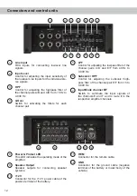
Страница 12: ... Control for adjusting the input sensitivity of the lowlevel Line Inputs for the individual ste reo signals 3 HPF Control for adjusting the highpass filter of the channel pairs A B and C D from 15 Hz to 4 000 Hz 4 X Over Switch for activating the filters for each channel pair 5 LPF Control for adjusting the lowpass filter of the channel pairs C D and E F from 40 Hz to 4 000 Hz 6 Subsonic HPF Contr...

Страница 13: ...ghpass filter the crossover frequency for the highpass can be adjusted with control 3 of the channel pair C D At switch position FULL fullrange the crossover is bypassed At switch position LPF lowpass filter bandpass the highpass is always active That means a band pass is created in any case By adjusting the highpass control 3 and lowpass filter control 5 of the channel pair C D any band pass betw...

Страница 14: ...ipped with several protection circuits These protections shut off the amplifier in case of overheat ing over and undervoltage short circuit on loudspeakers and false connection Please check for connecting failures such as short circuits wrong connections wrong adjustments and over tempera ture If the amplifier does not turn on it is defective and has to be sent to your local authorized dealer for ...

Страница 15: ... car audio system M SIX max 70 A RMS at 12 V power supply If your power wires are short less than 1 m 40 then a wire gauge of 10 mm AWG 8 will be sufficient In all other cases we strongly rec ommend gauges of 16 25 mm AWG 6 4 The ground cable same gauge as the 12 V wire should be connected to a common ground reference point this is located where the neg ative terminal of the battery is grounded to...

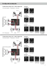
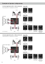
Страница 16: ... 2 VC Voice coil 50 100 Hz HPF HPF 50 100 Hz LPF Lowpass filter 50 100 Hz 5 channel application with 1 x 4 Ohms subwoofer Component system coaxial system subwoofer Left Right Left Right Front Rear Subwoofer Subwoofer E F bridged Summed Channel A B Highpass filter Channel E F Bandpass Summed Channel C D Highpass filter 50 100 Hz HPF HPF 50 100 Hz LPF Lowpass filter 50 100 Hz Summed Subsonic highpas...

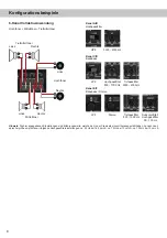
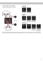
Страница 17: ... 70 Hz for 5 25 13 cm LS ca 100 Hz for 4 10 cm LS 6 channel fully active application Tweeters midrange speakers mid woofers Channel A B Highpass filter Channel E F Bandpass Stereo Channel C D Bandpass Left Right Left Right Mid woofers Midrange speakers Highpass filter 800 1000 Hz HPF LPF 3000 4000 Hz LPF Lowpass filter 800 1000 Hz Stereo Left Right Tweeters Lowpass filter 3000 4000 Hz Subsonic hig...

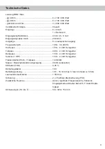
Страница 18: ... RCA Cinch 1 x Remote In Input sensitivity RCA Cinch 0 5 6 Volts Input impedance RCA Cinch 20 kOhms Outputs 6 x Speaker output Frequency response 10 Hz 30 000 Hz Highpass 15 Hz 4 000 Hz adjustable Lowpass 40 Hz 4 000 Hz adjustable Bandpass 15 Hz 4 000 Hz adjustable Subsonic HPF 15 Hz 4 000 Hz adjustable Slope high lowpass 12 dB Oct Signal to noise ratio analog input 98 dB A weighted Distortion THD...

Страница 19: ...19 Notizen Notes ...
Страница 20: ...Audiotec Fischer GmbH Hünegräben 26 57392 Schmallenberg Germany Tel 49 2972 9788 0 Fax 49 2972 9788 88 E mail helix audiotec fischer com Internet www audiotec fischer com ...

Отзывы: