background image

Helios PD2-6100 Strain Gauge, Load Cell, and mV Meter 

Instruction Manual 


48 


Internal Source Calibration (

ICAL

There is 

no need to recalibrate

 the meter when 

first received from the factory. 

The meter is 

factory calibrated

 prior to shipment 

for millivolts with calibration equipment that is 
certified to NIST standards.


The internal source allows the user to scale the meter 
without applying a signal. 
The use of calibrated signal sources is necessary to 
perform the internal source calibration of the meter. 
Check calibration of the meter at least every 
12 months. Each range must be recalibrated 
separately. 

Notes: 

1.  mV input: If meter is in operation and it is 

intended to accept only one input range  
(e.g. 0-30 mV), recalibration of other ranges is not 
necessary. 

2.  Strain gauge: If the meter is intended to accept a 

strain gauge bridge input, it is recommended to 
use the CAL function with ratiometric 
compensation turned on. 

3.  Allow the meter to warm up for at least 

15 minutes before performing the internal source 
calibration procedure. 


The 

Internal


calibration

 menu is part of the 

Advanced


Features

 menu.  

1.  Press and hold the Menu button for three 

seconds to access the advanced features of the 
meter. 

2.  Press the Up


arrow button to scroll to the 

Internal 

calibration

 menu (

ICAL

) and press Enter. 

3.  The meter displays the first input range (

15 nmV

), 

press the Up arrow to select any other range 
(e.g. 

100nmV

. Press Enter


to start the calibration 

process. 

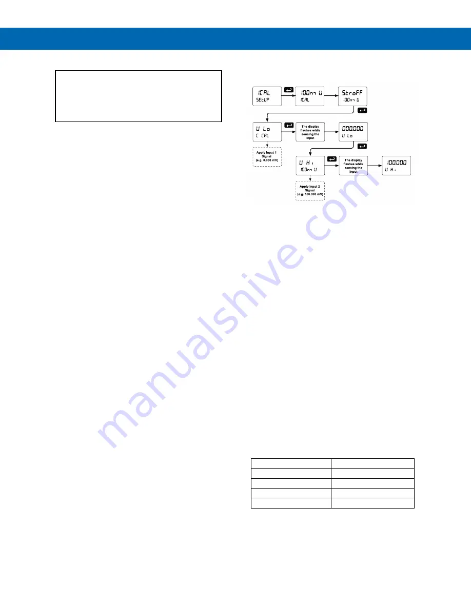
Example of Internal Calibration for 100 mV 
input range: 

4.  The meter displays 

the message “

stroff

” (strain 

offset), short the SG+, SG- terminals and press 
Enter. The 

low

 input message is displayed  

(

V lo

). Apply the low input signal (e.g. 0.00 mV) 

and press Enter. The display flashes for a 
moment while the meter is accepting the low 
input signal. 

5.  After the display stops flashing, a number is 

displayed with the leftmost digit brighter than the 
rest. The bright digit is the active digit that can be 
changed by pressing the Up


arrow button. Press 

the Right


arrow button to move to the next digit. 

6.  Set the display value to correspond to the input 

signal being calibrated; typically 0.00 mV. 

7.  The display moves to the 

high

 input calibration 

(

V Hi

). Apply the high input signal and press 

Enter. 

8.  Set the display for the high input calibration, in 

the same way as it was set for the low input 
calibration, typically 100.00 mV. 

The following graphic shows the calibration of the  
100 mV input range. The other ranges are calibrated 
in a similar way. 


Tips:


Low and high input signals can be any valid 
values within the range of the meter. 


Observe minimum input span requirements 
between input 1 and input 2. 


Low input should be less than high input 
signal. 

Error Message (

error

An error message indicates that the calibration or 
scaling process was not successful. 

After the error message is displayed, the meter 
reverts to input 2 during calibration or scaling and to 
input 1 during internal calibration, allowing the 
appropriate input signal to be applied or programmed. 
 

The error message might be caused by any of the 
following conditions: 

1.  Input signal is not connected to the proper 

terminals, or it is connected backwards. 

2.  Wrong signal selection in 

Setup

 menu. 

3.  Minimum input span requirements not 

maintained. 


Minimum Input Span 

The minimum input span is the minimum difference 
between input 1 and input 2 signals required to 
complete the calibration or scaling of the meter. 

Input Range 

Input 1 & Input 2 Span 

15 mV 

0.2 mV 

25 mV, 30 mV 

0.4 mV 

150 mV 

2.0 mV 

250 mV, 300 mV 

4.0 mV 

Содержание PD2-6100

Страница 1: ...g Software SunBright Display Standard Feature Great for Outdoor Applications Operating Temperature Range 40 to 65 C 40 to 149 F Conformal Coated PCBs for Dust and Humidity Protection UL C UL Listed E1...

Страница 2: ...te details Registered Trademarks All trademarks mentioned in this document are the property of their respective owners 2021 Precision Digital Corporation All rights reserved FREE MeterView Pro Program...

Страница 3: ...nfiguration 17 Shunt Calibration 19 Relay Connections 19 Switching Inductive Loads 19 RS 485 Connections 20 RS 485 Multi Drop Connection 20 RS 485 Serial Converters 20 Digital I O Connections 21 F4 Di...

Страница 4: ...put Aout 41 Reset Menu reset 41 Tare Menu Tare 41 Tare Functionality tare 41 Manual Control Menu Contrl 41 Setting Up the Password pass 42 Protecting or Locking the Meter 42 Making Changes to a Passwo...

Страница 5: ...Strain Gauge Powered by External Supply 18 Figure 15 Multiple Strain Gauges Connected Through Junction Box 18 Figure 16 mV Transducer Input Connections 18 Figure 17 Four wire mV Transducer Connections...

Страница 6: ...y loaded Helios PD2 6100 meter comes with four SPDT relays a 4 20 mA output one 10 VDC sensor excitation one 24 VDC power supply five digital inputs and four digital outputs and onboard RS 485 serial...

Страница 7: ...Red Yellow Green Light Layers Button Mounted and Wired to Helios 1 Note 1 Specify MOD PD2LH model as a separate item on the order for the Helios to order the Light Horn Button accessory installed and...

Страница 8: ...tal inputs Non Volatile Memory All programmed settings are stored in non volatile memory for a minimum of ten years if power is lost Power Options 85 265 VAC 50 60 Hz 90 265 VDC 20Wmax 12 24 VDC 12 24...

Страница 9: ...esistive load 1 14 HP 50 W 125 250 VAC for inductive loads Noise Suppression Noise suppression is recommended for each relay contact switching inductive loads see Switching Inductive Loads on page 19...

Страница 10: ...t to a 0 10 VDC output RS 485 Serial Communications Compatibility EIA 485 Connectors Removable screw terminal connector Max Distance 3 937 1 200 m max Status Indication Separate LEDs for Power P Trans...

Страница 11: ...es located under the lower door panel and are accessible by removing the single securing screw Wires should be run through the knockout holes located on the bottom of the meter see Figure 5 Conduit Ho...

Страница 12: ...e girth of the mounting screws pre drill holes at the mounting locations previously marked Insert mounting screws into the four mounting holes and screw them into the pre drilled holes DO NOT overtigh...

Страница 13: ...o the top and bottom for vertical pipes or left and right for horizontal pipes of the reverse side of the meter enclosure using the provided fasteners DO NOT overtighten the fasteners as it could caus...

Страница 14: ...Software Video at www predig com meterviewpro MeterView Pro Installation 1 Connect one end of the provided USB cable to the meter and the other end to the computer The computer will automatically inst...

Страница 15: ...sor requires 5 VDC excitation the switch labeled P P must be configured accordingly To access the voltage selection switch 1 Turn off the power to the meter 2 Unscrew and open the lower door panel 3 L...

Страница 16: ...f the lower door panel shows the location of all connectors available with the ordered configuration DO NOT connect any equipment to the RJ45 M LINK connector Otherwise damage will occur to the equipm...

Страница 17: ...urned ON the Helios s power supply is used Range Switch 2 The range switch adjusts the gain of the internal circuitry Narrower ranges require more amplification OFF Range Lower internal gain Turn this...

Страница 18: ...Connections The following figures show examples of strain gauge connections There is a 5 position DIP switch CONFIG to set up the input ranges and sensor excitation Note Refer to Switch Configuration...

Страница 19: ...when switching inductive loads to prevent disrupting the microprocessor s operation The snubbers also prolong the life of the relay contacts Suppression can be obtained with resistor capacitor RC netw...

Страница 20: ...meter 2 Press Up arrow until Serial SEriaL menu is displayed and press Enter Addres is displayed 3 Press Enter to change meter address using Right and Up arrow buttons Press Enter to accept 4 Press Me...

Страница 21: ...al Input Connections A digital input F4 is standard on the meter This digital input should be connected with a normally open contact across F4 and COM or with an active low signal applied to F4 It can...

Страница 22: ...activate the interlock relay This feature is enabled by configuring the relay and the corresponding digital input s see Setting Up the Interlock Relay Force On Feature on page 40 In the example below...

Страница 23: ...set the meter input selection See Switch Configuration on page 17 to setup the switch Setup and programming is done using MeterView Pro or through the programming buttons After power and input signal...

Страница 24: ...dvanced features of the meter Remote Buttons The meter can be operated via a remote control station PDA2364 MRUE using the digital input connections The PDA2364 MRUE mimics the Helios s four programmi...

Страница 25: ...CAL 1 Scale 1 Enter the Scale menu for PV1 SCAL 2 Scale 2 Enter the Scale menu for PV2 Display Functions Messages Display Parameter Action Setting Description Cal Calibrate Enter the Calibration menu...

Страница 26: ...Enter to reset min display Rst HL Reset high low Press Enter to reset max min displays Rst tr Reset tare Press Enter to reset tare tare Tare Enter Tare menu Captur Capture Press Enter to set meter to...

Страница 27: ...ressing Enter Setting Numeric Values The numeric values are set using the Right and Up arrow buttons Press Right arrow to select next digit and Up arrow to increment digit value The digit being change...

Страница 28: ...enu Setting the Display Units units Enter the pre defined engineering unit or custom unit The pre defined units have automatic conversion factors This unit will be displayed if d unit is selected as t...

Страница 29: ...l point at all Pressing the Right arrow moves the decimal point one place to the right until no decimal point is displayed and then it moves to the leftmost position Pressing the Up arrow moves the de...

Страница 30: ...the meter for at least 15 minutes before performing calibration to ensure specified accuracy Multi Point Calibration Scaling The meter is set up at the factory for 2 point linear calibration The numbe...

Страница 31: ...error message is displayed the meter reverts to input 2 during calibration or scaling and to input 1 during internal calibration allowing the appropriate input signal to be applied or programmed The...

Страница 32: ...g up the input and display press the Menu button to exit programming and skip the rest of the setup menu Press the Menu button again and the Up arrow to reach the Program menu and complete the scaling...

Страница 33: ...ime g Off relay state controlled by Interlock feature 2 Set point 3 Reset point 4 Fail safe operation a On enabled b Off disabled 5 Time delay a On delay 0 999 9 seconds b Off delay 0 999 9 seconds Se...

Страница 34: ...n safe limits and the relay coil is de energized when the alarm condition exists The fail safe operation is set independently for each relay Select on to enable or select off to disable fail safe oper...

Страница 35: ...lay coil is energized in non alarm condition In case of power failure relay will go to alarm state Time Delay Operation The following graphs show the operation of the time delay function When the sign...

Страница 36: ...ing Operation When the signal crosses the set point the relay trips and the sample time starts After the sample time has elapsed the relay resets The cycle repeats every time the set point is crossed...

Страница 37: ...atus indication for the following LED Status 1 Alarm 1 2 Alarm 2 3 Alarm 3 4 Alarm 4 The meter is supplied with four alarm points that include front panel LEDs to indicate alarm conditions This standa...

Страница 38: ...Manual reset any time Condition LED Relay Normal Off Off Alarm On On Ack Off Off Latching Relay with Clear Lt Clr In this application the meter is set up for manual reset only after the signal passes...

Страница 39: ...Function 1 30 000 10 000 Controls pump 1 2 35 000 5 000 Controls pump 2 3 4 000 9 000 Controls low alarm 4 40 000 29 000 Controls high alarm Pump Alternation Operation 1 Pump 1 turns on when level re...

Страница 40: ...lay Action menu and set the action to off 2 In the Advanced features User menu program any of the digital inputs to Force On any of the internal relays 1 4 3 Connect a switch or dry contact between th...

Страница 41: ...select the tare mode There are three modes of operation Capture Tare Programmable Tare and Off Capture Tare Pressing the Tare key zeroes the display and the T indicator flashes indicating that tare is...

Страница 42: ...on is pressed Press the Enter button while the message is being displayed and enter the correct password to gain access to the menu After exiting the programming mode the meter returns to its password...

Страница 43: ...on Advanced Features Menu Display Messages Display Parameter Action Setting SCALE Scale Scaling parameter SCAL 1 Scale 1 Scaling parameter 1 SCAL 2 Scale 2 Scaling parameter 2 CutofF Cutoff Set low va...

Страница 44: ...filter bypass may be set between 0 1 and 99 9 of full scale Rounding Feature round The rounding feature is used to give the user a steadier display with fluctuating signals Rounding is used in additi...

Страница 45: ...e programmed with up to 8 linearization points Auto Zero Auto 0 Auto zero corrects for drift that can occur over time that causes the input signal to slowly change The meter will continue to read zero...

Страница 46: ...ommended to use a milliamp meter with a resolution of at least 0 1 A to measure the output current The values saved internally during this procedure are used for scaling the 4 20 mA output in the Setu...

Страница 47: ...ion as they have been programmed O Hold Hold current relay states and analog output as they are until a button assigned to enable relays Rly E is pressed d Hold Hold the current display value relay st...

Страница 48: ...w input signal e g 0 00 mV and press Enter The display flashes for a moment while the meter is accepting the low input signal 5 After the display stops flashing a number is displayed with the leftmost...

Страница 49: ...value or other parameters function assigned through the User menu Function Keys Operation During operation the programmable function keys operate according to the way they have been programmed in the...

Страница 50: ...hrough all digits decimal points and relay indicators to enable the operator to check that all LEDs are functioning properly 4 Press the Enter button again to access the Information menu info or press...

Страница 51: ...0 Relay 4 reset point RSt 4 35 00 Fail safe relay 1 Fls 1 Off Fail safe relay 2 Fls 2 Off Fail safe relay 3 Fls 3 Off Fail safe relay 4 Fls 4 Off Parameter Display Default Setting On delay relay 1 On...

Страница 52: ...1 Input selected in Setup menu 2 Signal at Signal connector 3 Input exceeds range selected Display is unstable Check 1 Input signal stability and value 2 Display scaling vs input signal 3 Filter and b...

Страница 53: ...8990 www predig com LIM2 6100_D SFT071 Ver 4 211 up 08 21 Contact Precision Digital Technical Support Call 800 610 5239 or 508 655 7300 Fax 508 655 8990 Email support predig com Sales Support Call 80...

Отзывы: