Installation
Suprasetter A52/A75 – Installation
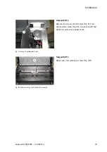
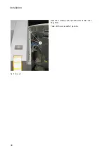
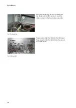
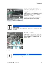
Fig. 34 Motor shaft viewed from inside
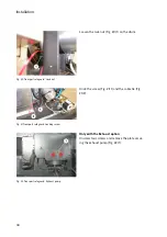
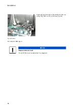
Fig. 35 Covering
Fig. 36 X69
Fit the cover (Fig. 35/1) and the bezel (Fig. 35/2).
Route adapter X22 / X69 to the electronics box.
Start at the swivel area of the rotary table/the opto
switch lug and secure with cable ties.
The cable between connector X69 (Fig. 36/1) and
cable tie (Fig. 36/2) should be 220 mm long.
Plug connector X69 (Fig. 36/1) to motor M80.
Содержание Suprasetter A52
Страница 6: ......
Страница 24: ...Safety 22 Fig 24 Filter replacement Fig 13 4 On the filter unit ...
Страница 26: ...Safety 24 Fig 26 Warning sign copy template ...
Страница 36: ...Installation Preparation 34 Pallet Installation Instructions ...
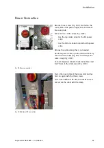
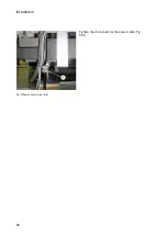
Страница 60: ...Installation 58 Fig 51 Power cable strain relief Tighten the strain relief for the power cable Fig 51 1 ...
Страница 82: ...Technical Data 80 Resolution 1000 pixels cm 2540 dpi Type Value Comment ...
Страница 84: ......
Страница 85: ......

