Installation
Suprasetter A52/A75 – Installation
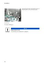
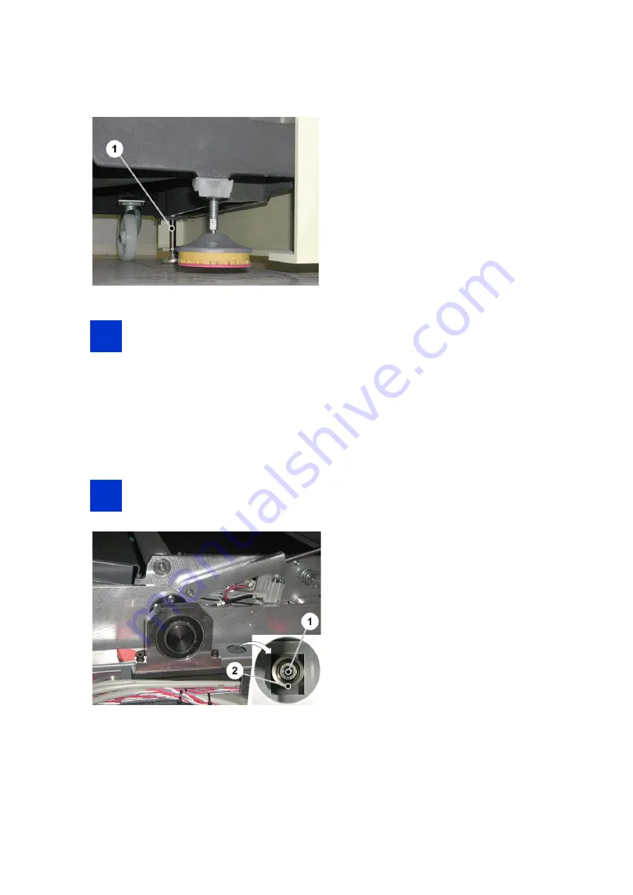
Fig. 28 Chassis feet
Note:
The screws shown in Fig. 26 remain loosened by 3 to 4 turns.
Screw the chassis feet in until the Suprasetter only rests on the 3 rubber feet of the cast base.
Screw the chassis feet down again until they make contact with the floor, tighten them by hand, give
an extra 1/4 turn and lock them.
Checking Centering
Note:
Both doors of the Suprasetter must be closed.
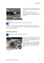
Fig. 29 Centering
Screw down the two chassis feet (Fig. 28/1) at the
front of the Suprasetter to slightly raise the Supra-
setter.
Remove the spacer sleeves (Fig. 27/1).
Pull out the brackets (Fig. 26/1) sideways under-
neath the chassis on the left and right side of the
Suprasetter.
The ring (Fig. 29/1) should be in the center on both
sides in the recess (Fig. 29/2). The recess is rect-
angular on one side of the Suprasetter and square
on the other side.
Check the clearance on both sides of the Supra-
setter by pushing the chassis (supported on rubber
blocks) to the front, to the rear and to both sides.
The two rings must not touch the edge of the
recess.
i
i
i
i
Содержание Suprasetter A52
Страница 6: ......
Страница 24: ...Safety 22 Fig 24 Filter replacement Fig 13 4 On the filter unit ...
Страница 26: ...Safety 24 Fig 26 Warning sign copy template ...
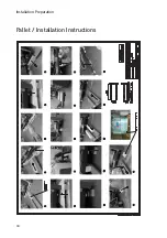
Страница 36: ...Installation Preparation 34 Pallet Installation Instructions ...
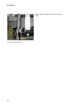
Страница 60: ...Installation 58 Fig 51 Power cable strain relief Tighten the strain relief for the power cable Fig 51 1 ...
Страница 82: ...Technical Data 80 Resolution 1000 pixels cm 2540 dpi Type Value Comment ...
Страница 84: ......
Страница 85: ......

