HEBI Robotics Rosie Скачать руководство пользователя страница 10

X-Series Rosie Assembly Instructions

10

Chassis

Содержание Rosie

Страница 1: ...Rosie 6 DoF Arm w Gripper on Omni Directional Base Assembly Instructions ...

Страница 2: ...uator Comply with the operating temperature 10 to 50 Turn off power source before connecting or disconnecting actuator power Do not expose the actuator to permanent and strong magnetic fields The actuator must not be exposed to dusty or wet environments If actuator is under load abruptly removing the power connection can cause permanent damage Do not force screws into the bottom of the actuator X5...

Страница 3: ...Robot Workspace X Series Rosie Assembly Instructions 3 Top View Wheel Base 0 5m Side View Max Reach 0 750m Half Reach 0 375m ...

Страница 4: ...ayload 3 75 kg Max Speed with X8 3s 1 0 m s Movement Working Range Speed Axis 1 Base Default X8 9 Continuous limited by wiring 180 s Axis 2 Shoulder Default X8 9 0 to 70 limited by gas spring 180 s Axis 3 Elbow Default X5 9 155 to 155 avoid end effector collisions 84 s Axis 4 Wrist 1 Default X5 1 Continuous avoid end effector collisions 540 s Axis 5 Wrist 2 Default X5 1 Continuous limited by wirin...

Страница 5: ...79 5mm Technical Specifications X Series Rosie Assembly Instructions 5 82mm 113mm 105 35mm 8mm 12mm 23mm 4 X M3 THRU 4 X M3 THRU 10mm 10mm 10mm 5mm ...

Страница 6: ...Housing 1 x PM 2292 01 Spool 1 x PM 2290 01 Cable Clamp 1 x PP 2240 01 Cable Housing 1 x PM 2222 01 Cable Housing Adapter part of A 2055 01 1 x PP 2241 01 Cable Housing End Cap Default Configuration 3 x X5 1 1 x X5 9 3 x X8 3 2 x X8 9 1 x X8 16 2 x A 2039 02 2 x A 2091 01 2 x A 2038 02 2 x A 2090 01 4 x A 2043 01 2 x PM 2200 02 300mm 1 x PP 2239 01 Cable 1 x A 2055 01 Gripper Assembly 2 x A 2042 0...

Страница 7: ...ns 7 4 x A 2046 12 Power Cable 12 Length 3 x A 2046 18 Power Cable 18 Length 3 x A 2046 24 Power Cable 24 Length 5 x PP 2059 01 Ethernet Cable 12 Length 2 x PP 2061 01 Ethernet Cable 36 Length 3 x A 2128 01 Power Distribution Board up to 4 x PP 2084 01 LiGo Battery ...

Страница 8: ...o fit ethernet and power connectors Please pass connectors thru bore hole one at a time For more information visit docs hebi us X Series Rosie Assembly Instructions 8 Spiral sleeving Wires that come from the previous joint should be inserted directly to actuator ports Wires that connect to the next joint should be threaded through the actuator s bore hole Power distribution boards are included to ...

Страница 9: ...Table of Contents Assembly Quantity Image Pages Chassis 1x 10 14 6 DoF Arm Kit 1x 15 23 Gripper 1x 24 27 Final 1x 28 39 X Series Rosie Assembly Instructions 9 ...

Страница 10: ...X Series Rosie Assembly Instructions 10 Chassis ...

Страница 11: ...ctions 11 20 T slot nut 20 x BHCS 3 x X8 3 3 x A 2043 01 M5x10mm FHCS Wheel 1 X8 3 x y 1 2 3 Wheel 2 X8 3 Wheel 3 X8 3 Rubber bumpers will need to be removed in order to slide in T slot nuts 1 x A 2127 01 Hexagonal Wireless Chassis ...

Страница 12: ...X Series Rosie Assembly Instructions 12 M4x55mm M5x8mm 3 x A 2076 01 Wheel Adapter 3 x PP 2185 01 6 Omni Wheel ...

Страница 13: ...Chassis Wiring X Series Rosie Assembly Instructions 13 Power Cable Ethernet Cable Battery Legend Wheel 2 Wheel 3 Wheel 1 Cabling will be provided with assembled chassis ...

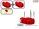
Страница 14: ...Chassis Bulkhead Layout X Series Rosie Assembly Instructions 14 ...

Страница 15: ...6 DoF Arm Kit right inside X Series Rosie Assembly Instructions 15 ...

Страница 16: ...2 x X Series Rosie Assembly Instructions 16 1 x PP 2200 02 300mm 1 x A 2038 02 1 x A 2039 02 M5x16mm M5x16mm ...

Страница 17: ...s 17 Axis 1 Base Default X8 9 Step 1 of 2 Step 2 of 2 M6x10mm M5x12mm M5x10mm FHCS 1 x X8 9 Flat face towards inside Align with actuator output hub tick mark face parallel with tick mark and mounting hole pointed on same side 1 x A 2040 01R ...

Страница 18: ...X Series Rosie Assembly Instructions 18 Axis 2 Shoulder Default X8 16 1 x 1 x M5x14mm 1 x X8 16 ...

Страница 19: ...X Series Rosie Assembly Instructions 19 1 x 1 x 1 x M5x10mm Align with actuator output hub tick mark Tube aligns with tick mark ...

Страница 20: ...X Series Rosie Assembly Instructions 20 1 x 1 x 1 x M5x10mm M5x8mm Axis 3 Elbow Default X8 9 Align with actuator output hub tick mark Tube aligns with tick mark 1 x X8 9 ...

Страница 21: ...X Series Rosie Assembly Instructions 21 1 x 2 x X5 1 1 x A 2042 01R M5x12mm M5x10mm Axis 4 Wrist 1 Default X5 1 M5x8mm Axis 5 Wrist 2 Default X5 1 Align with actuator output hub tick mark ...

Страница 22: ...X Series Rosie Assembly Instructions 22 1 x 1 x X5 1 1 x A 2042 01R M5x12mm M5x10mm Axis 6 Wrist 3 Default X5 1 Align with actuator output hub tick mark ...

Страница 23: ...X Series Rosie Assembly Instructions 23 All axes at zero degrees ...

Страница 24: ...Gripper X Series Rosie Assembly Instructions 24 ...

Страница 25: ...X Series Rosie Assembly Instructions 25 1 x X5 9 Spool Default X5 9 ...

Страница 26: ...X Series Rosie Assembly Instructions 26 1 x PM 2293 01 Spool Housing 1 x PM 2292 01 Spool M5x12mm M3x35mm Clocking for the Spool does not matter ...

Страница 27: ...X Series Rosie Assembly Instructions 27 1 x PM 2290 02 Housing Horizontal Tube Adapter M5x8mm ...

Страница 28: ...X Series Rosie Assembly Instructions 28 Final Assembly ...

Страница 29: ...X Series Rosie Assembly Instructions 29 2 x PM 2148 01 Tube Clamp ...

Страница 30: ...X Series Rosie Assembly Instructions 30 M5x8mm Align with actuator output hub tick mark Fingers perpendicular to the tick mark The Last Module on the Arm 1 x A 2055 01 Gripper Assembly ...

Страница 31: ...ies Rosie Assembly Instructions 31 Wiring Diagram Power Cable Ethernet Cable Power Distribution 24 18 12 12 18 18 24 12 36 36 12 12 12 12 Base Shoulder Elbow Wrist 1 Wrist 2 Wrist 3 Spool 24 12 12 To Chassis ...

Страница 32: ... 20 x BHCS 20 80 20 T Nut X Series Rosie Assembly Instructions 32 The arm must be wired before this step ...

Страница 33: ...to subassembly wiring diagrams X Series Rosie Assembly Instructions Wheel 1 Wheel 2 Wheel 3 Power Cable Ethernet Cable Power Distribution Battery Ethernet Coupler Legend 24 Base Shoulder Elbow Wrist 1 Wrist 2 Wrist 3 Spool 12 ...

Страница 34: ...re that the cable is long enough Cut the cable housing first and then cut the cable X Series Rosie Assembly Instructions 34 Cable Housing minimum bend radius 25mm 100mm About 100mm of Cable should stick out from the Cable Housing Make sure that the Cable Housing is long enough to be fully inserted into the Housing End Cap and the Housing Adapter Cross Section View of the Cable ...

Страница 35: ...X Series Rosie Assembly Instructions 35 1 x PP 2239 01 Cable 1 x PP 2240 01 Cable Housing 1 x PM 2222 01 Cable Housing Adapter ...

Страница 36: ...36 Gripper Cable Routing X Series Rosie Assembly Instructions ...

Страница 37: ...X Series Rosie Assembly Instructions 37 ...

Страница 38: ...X Series Rosie Assembly Instructions 38 1 x PM 2290 01 Cable Clamp M3x8mm ...

Страница 39: ...X Series Rosie Assembly Instructions 39 M2x8mm 2 x A 2091 01 2 x A 2090 01 M2x8mm Install all cables before attaching covers M2x8mm 1 x A 2090 01 ...

Страница 40: ...X Series Rosie Assembly Instructions 40 HEBI Robotics 2018 ...

Отзывы: