6.
.
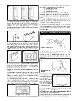
7. Remove the front panel by removing the two self tapping
screws along its bottom edge. With hands positioned on
each side of the panel, lift upwards to unhook the top edge
whilst pressing down on the top panel with your thumbs.
Ensure the convector element is not damaged when placing
this panel on one side.
7.
8. Remove the inner front by removing the screws along its
top and sides. As the front insulation is attached care must be
taken when lifting this panel from the heater and placing it to
one side. Remove the internal packaging by sliding it up and
off the elements taking care not to damage the insulation.
9. Remove one element to allow access for the back rows of
bricks. On the 24 remove the element to the right of centre,
on the 18 remove the central element, on the 12 the left
hand element should be removed.
Loosen the two screws securing the element up and out
of the heater.
10. Carefully
fi
t the bottom row of the back layer of bricks
placing the two end bricks in position
fi
rst with the recess
towards the element. Fit the top row of bricks also with the
recess towards the element.
11. Re
fi
t the element which had been removed by feeding
the tails down through the hole in the base insulation and
into the connector block. Ensure the element is fully pushed
home then securely tighten the two screws in the block.
12. Fit the front layer of bricks again with the recess towards
the element. The complete core will comprise:
12 - 2 x 4 Brick Columns
18 - 3 x 4 Brick Columns
24 - 4 x 4 Brick Columns
13. Replace the inner front complete with insulation by
locating its bottom edge behind the front lip of the chas-
sis and inserting retaining screws along the top and both
sides.
14. Check that the
fl
ap mechanism operates freely on its
hinges and that with the output control at minimum the
fl
ap
is correctly seated in its closed position.
15.
Connection of Storage Supply
- Feed the mains
through the cable clamp and make connections as marked
on heater. Pull back any slack through the clamp and tighten
clamping screw.
Warning - This appliance must be earthed.
15.
15. Connection of supply to convector is through a cable
clamp in the base of the front panel.
Connect the wires as detailed below, pull back any slack
through the cable clamp and tighten clamping screw, see
picture 16.
1 7 .
R e p l a c e o u t e r
front panel and grille by
hooking the grille into its
retaining
slot on the top
panel and lowering it
into position. Secure the
front panel with the two
self tapping screws.
18. Check that the screws securing the heater to the wall
bracket have been fully tightened.
IT IS ESSENTIAL THAT ALL SCREWS ARE REPLACED
TO ENSURE EARTH CONTINUITY.
Once installed do not attempt to reposition the heater without
fi
rst obtaining the services of a competent electrician.
11.
8.
RESTRICTED SUPPLY
16.
17.
9.
UNRESTRICTED
SUPPLY


