The differential equation of the sprin g-m ass system shown in Figure 29 is
M ^
+
s d f + K y = F l , )
with
y (o) =
(o) = o .
d t
The last expression states that the displacem ent at time equals z ero (the start of the problem
solution) y (o) and the velocity at time equals z ero
(o) are both zero.
The differential equation may be written
M s T T = F< » - s 7 r - “ v
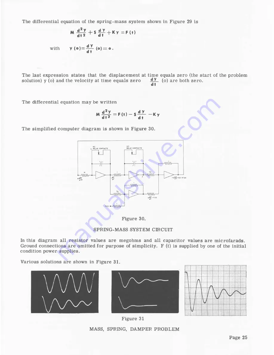
The sim plified computer diagram is shown in Figure 30.
Figure 30.
SPRING-MASS SYSTEM CIRCUIT
In this diagram all re sisto r values are megohms and all capacitor values are m icrofarads.
Ground connections are omitted fo r purpose of sim plicity. F (t) is supplied by one of the initial
condition power supplies.
Various solutions are shown in Figure 31.
Figure 31
MASS, SPRING, DAMPER PROBLEM
Page 25


