


26
Optional Controls
E. Copeland Demand Cooling for Discus L6 Models
Energy efficiency regulations drive continuous change in the availability of refrigerants
to the marketplace. With the introduction of R-22 as a replacement for R-502
compressors began to experience internal discharge temperatures that exceed the
safe operational limits for long term stability of refrigerant oil. In response to this
Demand Cooling was developed as a reliable method to keep discharge temperatures
reduced to a safe level without inhibiting the operating limits of the compressor. With
the phase out of R-22, the following refrigerants have become viable alternatives:
R-407A/C/F and R-448A/449-A. All of these refrigerants require special attention to
discharge temperature control. Also forthisreasonsuctiontoliquid heat exchangers are
not recommended unless they are necessary to prevent another potential problem.
The Copeland Demand Cooling System
Copeland's demand cooling system uses modern electronics to provide a
reliable, cost-effective solution to this problem. It is required for all single
stage required for all single stageR-22,R-407A/C/ForR-448A/449-A applications
with saturated suction temperatures below 0˚F.
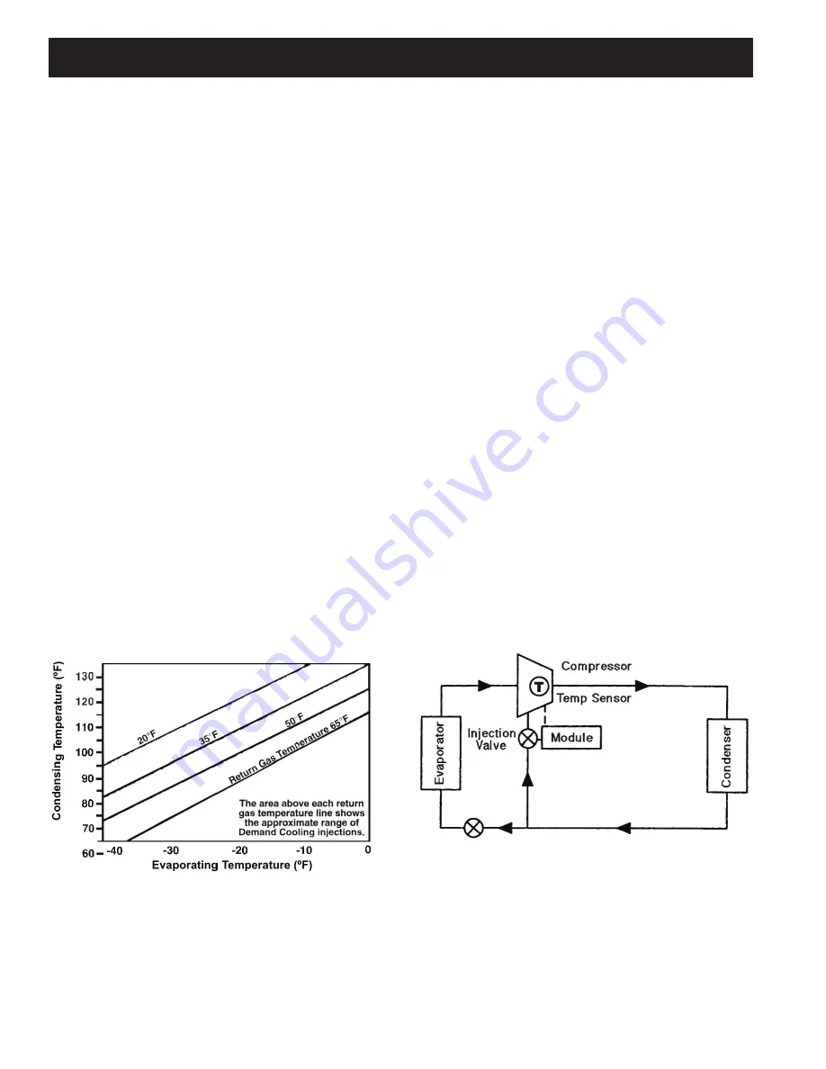
The Demand Cooling module uses the signal of a discharge head temperature
sensor to monitor discharge gas temperature. If a critical temperature is reached,
the module energizes along life injection valve which meters a controlled amount of
saturated refrigerant into the compressor suction
cavity to cool the suction gas. Refer to Figure 13.
This process controls the discharge temperature to a safe level. If, for some
reason, the discharge temperature rises above a preset maximum level,
the Demand Cooling module will turn the compressor off (requiring a manual reset)
and actuate its alarm contact. To minimize the amount of refrigerant which must
be injected, the suction gas cooling process is performed after the gas has passed
around and through the motor.
Operating Range
Demand Cooling is designed to protect the compressor from high discharge
temperatures over the evaporating and condensing temperature ranges shown in
Figure 12 at a maximum return gas temperature of 65˚F.
Figure 12. Demand Cooling Injection
Demand Cooling System Design
When Demand Cooling operates, it “diverts” refrigeration capacity in the form of
injected saturated refrigerant from the evaporator to the compressor. The effect of this
diversion on evaporator capacity is minimal because the diverted capacity is used to
cool the gas entering the compressor. As the gas is cooled, it naturally becomes more
dense, increasing the mass flow through the compressor, which partly compensates
for the capacity diverted from the evaporator.
1. Compressor Return Gas Temperature: Suction lines should be well
insulated to reduce suction line heat gain. Return gas superheat
should be as low as possible consistent with safe compressor
operation.
2. Condensing Temperatures: It is important when using R-22, R-407
A/C/F or R-448A/449A as a low temperature refrigerant that
condensing temperatures be minimized to reduce compression ratios
and compressor discharge temperature.
3. Suction Pressure: Evaporator design and system control settings
should provide the maximum suction pressure consistent with the
application in order to have as low a compression ratio as possible.
In most cases, with floating head systems where condensing temperatures
are low during most of the year, Demand Cooling will operate primarily as
a compressor protection control much as the oil failure control protects the
compressor during periods of low oil pressure. Demand Cooling will be
allowed to operate only during those periods when condensing temperatures
and return gas temperatures are high or in periods where a system failure
(such as an ice evaporator, an expansion valve which does not control superheat,
blocked condenser, or a failed condenser fan) raises condensing temperatures or
return gas temperatures to abnormally high levels or lowers suction pressure to
abnormally low levels.
Figure 13. Single Stage Internal Refrigerant Injection
Содержание Mohave
Страница 13: ...13 Piping The following are examples of proper piping layout for typical system configurations...
Страница 14: ...14 Piping...
Страница 38: ...38 Standard Independent Evaporator Power Supply with VFD Condenser Fans Wiring Diagram...
Страница 39: ...39 Standard Independent Evaporator Power Supply with VFD Condenser Fans Wiring Diagram...
Страница 45: ...45 Defrost Operation Black Piping Inactive Gray Piping Active Hot Gas Defrost Cycle Diagrams...
Страница 46: ...46 Defrost Operation Black Piping Inactive Gray Piping Active Hot Gas Defrost Cycle Diagrams...
Страница 75: ...75 Notes...


