


14
PREPARATION
CONNECTION
COLD
EXPANSION
COLD WATER
CHECK
HOT WATER
VALVE
GAS
HOT WATER
INLET
PREVENTER
BACKFLOW
TANK
HOT WATER
BALL VALVE
SHUT-OFF
HOT WATER
AUXILIARY
OUTLET
COLD WATER
COLD WATER
GAS
AUXILIARY
CONNECTION
GAS
CIRCULATOR
(SEE NOTE 4)
LP-179-N
7/16/07
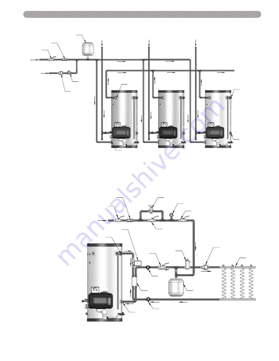
NOTE:
This drawing is meant to show system piping
only. The installer is responsible for all
equipment and detailing required by local codes.
REVERSE MANIFOLD AND PIPING DIAGRAM FOR PHOENIX
NOTES:
1. Minimum pipe size should match
connection size on Phoenix. If
you require greater flow, upsize
the pipe accordingly.
2. A Thermal Expansion tank
suitable for potable water must
be sized and installed within this
piping system between the
check valve and the cold water
inlet of the Phoenix.
Check with the Manufacturer of
the Thermal Expansion tank for
proper sizing.
3. Gas Line must be rated to the
maximum input capacity of the
unit. Unit must have 10 feet of
pipe after gas regulator.
4. All circulators shall have an
integral flow check.
NOTE:
This drawing is meant to show system piping only. The installer is responsible for all
equipment and detailing required by local codes.
VALVE
BACKFLOW
PREVENTER
VALVE
PURGE
PLATE
BRAZED
CLOSED LOOP RADIANT HEATING
AIR
ELIMINATOR
BALL
VALVE
AUXILIARY
GAUGE
PRESSURE
RADIANT
HEAT
VALVE
BALL
CONNECTION
PRESSURE REDUCING
VALVE
BALL
TANK
EXPANSION
WATER
MAKE-UP
VALVE
BALL
AUXILIARY
CONNECTION
SYSTEM
DRAIN
CIRCULATOR
( see note 4)
CIRCULATOR
(See note 4)
LP-179-U
7/13/07
CLOSED LOOP RADIANT HEATING
NOTES:
1. Minimum pipe size should
match connection size
on Phoenix. If you require
greater flow, upsize the
pipe accordingly.
2. A Thermal Expansion
tank suitable for potable
water must be sized and
installed within this piping
system between the
check valve and the
cold water inlet of the
Phoenix.
3. Gas Line must be rated
to the maximum input
capacity of the unit. Unit
must have 10 feet of
pipe after gas regulator.
4. All circulators shall have
an integral flow check.