Mortex Products Inc. / Fort Worth, TX 76106
G18D Installation Instructions
!
WARNING
!
WARNING
G18D Series Gas Furnace
INSTALLATION INSTRUCTIONS
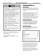
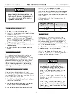
To avoid electric shock, personal injury, or
death, turn off the power at the disconnect
or the main service panel before making
any electrical connections.
NOTE: The use of 18-gauge wire is highly
recommended to carry the thermostat load. Use of
smaller conductors risks operational problems caused by
loose or broken conductors or wire that is too small to
carry the load. Any such problems are the responsibility
of the installer.
With conductors smaller than 18-gauge, observe the
following guidelines.
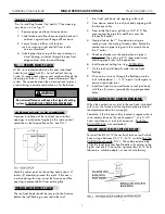
Maximum Thermostat wire
Length (furnace to thermostat) Thermostat wire gauge
0–45 feet
22
0–70 feet
20
9
WALL THERMOSTATE
The location of the wall thermostat is important, as it
must sense the desired temperature of the entire
conditioned space. Choose a location 4–5 feet above
the floor, preferably on an inside wall in an area with
good air circulation. Stay away from lamps and air
registers and do not install behind a door. Choose a
location where the temperature will be reasonably
representative of other living areas the thermostat is
controlling.
CONNECT THERMOSTAT WIRES
When installing a furnace with a cooling coil
compartment, use of a five-connector thermostat cable is
recommended. This will allow easy installation of an air
conditioning system at a later date.
1. Insert 24V wires through the small plastic bushing on
the left side of the furnace.
2. Connect low voltage wires to the color coded low
voltage pigtails at the of the control panel.
3. Connect low voltage wires to the wall thermostat.
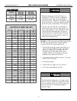
GAS PIPING
Supply piping must be sized in accordance with
recommendations found in National Fuel Gas Code
ANSI Z223.1/NFPA-54. In addition materials used in
manufactured homes must comply with requirements
contained in HUD Title 24, Section 3280.705 as well as
A119.2 for recreational vehicles.
See Chart in this manual for minimum sizes for NAT and
LP pipe and tubing serving the furnace only.
NOTE: The gas inlet on the gas control valve is 1/2-
14NPT. The gas line may be installed through the bottom
casing or on left or right side of furnace.
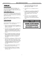
Take care when connecting the gas line to the
furnace gas valve. Use suitable wrenches to
support the gas valve when tightening fittings to
prevent mis-alignment of the attached burner
orifice. Do not damage the gas valve as improper
heating, exsplosion, fire or asphyxiation may
result.
Do not use matches, lighters, candles or other open
flame to check for leaks. Use soap or water solution
or a leak detector.
Do not test the fuel system at more than 14” W.C.
pressure once furnace has been connected to the
gas line. Over pressure may void the warranty and
damage the valve which could cause an explosion,
fire or asphyxiation.
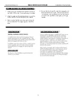
CONNECT POWER SUPPLY
1. Remove the furnace control panel cover.
2. Insert 115 V wiring through a strain relief bushing on
the left side of the furnace.
3. Connect the HOT wire to the black pigtail lead;
connect the NEUTRAL wire to the WHITE pigtail
lead. Secure the connections with suitable wire nuts
and wrap with electrical tape. Refer to Wiring
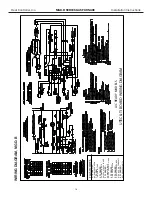
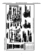
Diagram on pg. 12 for connections.
4. Connect the GROUND wire to a grounding screw in
the control panel.
5. Reinstall and secure the control panel cover with
screws.
Installation Instructions
MGD-B SERIES GAS FURNACE
Heat Controller, Inc.
9
Содержание MGD60-E3B
Страница 3: ...Heat Controller Inc MGD B SERIES GAS FURNACE Installation Instructions 2...
Страница 9: ...Heat Controller Inc MGD B SERIES GAS FURNACE Installation Instructions 8...
Страница 14: ...Installation Instructions MGD B SERIES GAS FURNACE Heat Controller Inc 13...
Страница 17: ...04 2009 7 2009...


