7
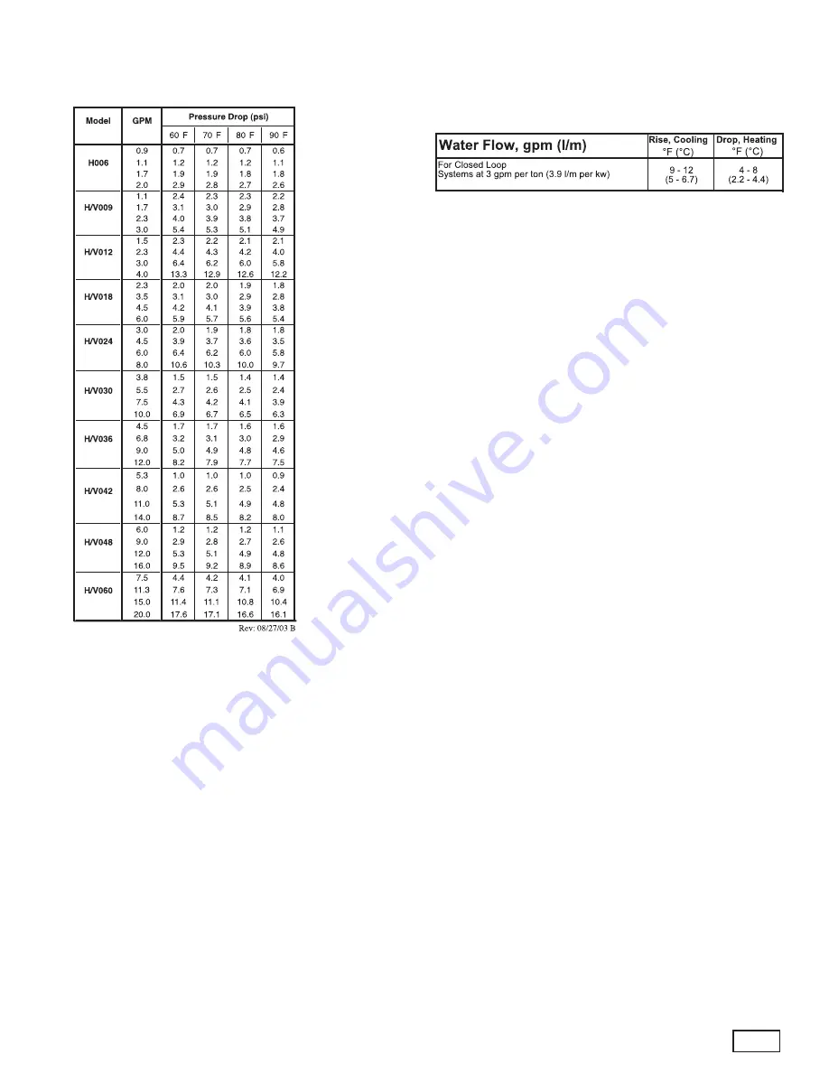
Table 8e: HCH_HCV Coax Water Pressure
°
UNIT OPERATING CONDITIONS
Table 9: Water Temperature Change Through Heat Exchanger
Страница 1: ...ns Commercial Water Source Heat Pumps HEAT CONTROLLER INC 1900 Wellworth Ave Jackson Michigan 49203 Ph 517 787 2100 Fax 517 787 9341 www heatcontroller com THE QUALITY LEADER IN CONDITIONING AIR Insta...
Страница 2: ...and High Static Z Straight and High Static Y Back and High Static 1 2 3 456 7 8 9 10 11 12 13 14 Table of Contents Model Nomenclature 1 Storage 3 Pre Installation 3 Physical Data 4 Dimensional Data 5...
Страница 3: ...ts as a source of heating or cooling during the construction process The mechanical components and filters will quickly become clogged with construction dirt and debris which may cause system damage W...
Страница 4: ...the unit and its operation Thoroughly check the system before operation Prepare units for installation as follows 1 Compare the electrical data on the unit nameplate with ordering and shipping inform...
Страница 5: ...x 24 610 x 610 24 x 24 610 x 610 1 14 x 24 1 18 x 24 Weight Operating lbs kg 103 47 105 48 114 52 181 82 189 86 197 89 203 92 218 99 263 119 278 126 Weight Packaged lbs kg 113 51 115 52 124 56 186 84...
Страница 6: ...0 8 1 8 0 8 1 2 8 1 5 1 2 1 0 8 8 9 6 7 5 2 1 3 16 1 9 8 1 1 0 6 cm 48 5 86 6 27 9 24 4 2 0 4 4 2 0 20 6 13 0 5 4 1 9 22 7 17 0 13 3 3 3 41 0 25 0 2 7 1 5 018 in 20 1 43 1 17 1 15 3 2 4 1 9 2 1 1 2 12...
Страница 7: ...5 55 9 3 6 7 1 24 0 7 1 15 6 5 9 7 3 14 9 22 5 22 7 12 9 22 9 22 9 14 0 5 3 41 1 25 1 1 9 018 in 21 5 21 5 39 0 1 8 3 8 15 2 3 6 8 1 2 3 1 2 4 1 7 1 10 1 6 4 3 8 14 0 14 0 5 3 2 3 18 3 20 2 0 7 cm 54...
Страница 8: ...electrical cables and other items that prohibit future removal of components or the unit itself 4 Use a manual portable jack lift to lift and support the weight of the unit during installation and se...
Страница 9: ...ower Disconnect Power Wiring Insulated supply duct with at least one 90 deg elbow to reduce air noise Return Air Supply Air Unit Hanger 3 8 10mm threaded rods Unit Power Flexible Duct Connector Figure...
Страница 10: ...position as shown being careful with the blower wiring 3 Check blower wire routing and connections for tension or contact with sheet metal edges Reroute if necessary 4 Check refrigerant tubing for con...
Страница 11: ...19mm ID plastic hose Insure that the hose is without kinks to maintain unobstructed flow of condensate from the unit to the drain Verify that condensate line is pitched towards the drain 1 4 per foot...
Страница 12: ...eyond all four edges of the unit 2 Provide adequate clearance for filter replacement and drain pan cleaning Do not block filter access with piping conduit or other materials Refer to unit submittal da...
Страница 13: ...r neoprene isolation pad to minimize vibration transmission to the building structure Figure 9 Vertical Sound Attenuation Condensate Piping Vertical Units Vertical units utilize a condensate hose insi...
Страница 14: ...compound is preferred use compound only in small amounts on the external pipe threads of the fitting adapters Prevent sealant from reaching the flared surfaces of the joint Note When anti freeze is us...
Страница 15: ...ed pumping systems may also be included in the external piping The piping system should be flushed to remove dirt piping chips and other foreign material prior to operation see Piping System Cleaning...
Страница 16: ...s are OK to 0 5 ppm Ammonia ion All 0 5 ppm as hydroxide chloride nitrate and sulfate compounds Maximum Maximum Allowable at maximum water temperature Chloride Levels 50 F 10 C 75 F 24 C 100 F 38 C Co...
Страница 17: ...0 1 80 7 5 8 9 15 5 575 60 3 518 633 1 4 7 39 0 1 40 6 1 7 2 15 1 208 230 60 1 197 254 1 25 6 170 0 4 30 29 9 36 4 60 V H060 3 208 230 60 3 197 254 1 14 7 124 0 4 30 19 0 22 7 35 4 460 60 3 414 506 1...
Страница 18: ...size Grnd Rev 5 17 01 B Capacitor WARNING Disconnect electrical power source to prevent injury or death from electrical shock 208 Volt Operation All commercial 208 230 Volt units are factory wired fo...
Страница 19: ...mostat should be wired directly to the CXM board Figure 19 Low Voltage Field Wiring Low Water Temperature Cutout The CXM control senses low water temperature utilizing thermistor FP1 Note that the FP1...
Страница 20: ...60 seconds to open very little water will flow before 45 seconds Once fully open an end switch allows the compressor to be energized Only relay or triac based electronic thermostats should be used wit...
Страница 21: ...ermostat wires protrude through the middle of the back plate Mark the position of the back plate mounting holes and drill holes with a 3 16 5mm bit Install supplied anchors and secure plate to the wal...
Страница 22: ...21 TYPICAL WIRING DIAGRAM HCH HCV UNITS WITH CXM BOARD SINGLE PHASE...
Страница 23: ...Description of Operation LED Alarm Relay Normal Mode On Open Normal Mode with UPS Warning On Cycle closed 5 sec Open 5 sec CXM is non functional Off Open Fault Retry Slow Flash Open Lockout Fast Flash...
Страница 24: ...ds normal operation is restored This is not considered a fault or lockout If the CXM is in over under voltage shutdown for 15 minutes the alarm relay will close Over under voltage shut down code 7 Uni...
Страница 25: ...gle most important step to insure proper start up and continued efficient operation of the system Follow the instructions below to properly clean and flush the system 1 Insure that electrical power to...
Страница 26: ...and adjust water pH if necessary to maintain a level between 6 and 8 5 Proper pH promotes longevity of hoses and fittings see table 3 System flushing Verify that all hoses are connected end to end wh...
Страница 27: ...thermostat to the lowest setting Place the thermostat mode switch in the HEAT position b Slowly raise the thermostat to a higher temperature until the compressor activates c Check for warm air deliver...
Страница 28: ...27 Table 8e HCH_HCV Coax Water Pressure UNIT OPERATING CONDITIONS Table 9 Water Temperature Change Through Heat Exchanger...
Страница 29: ...per Sub Temp Temp Pressure Pressure Super Sub Temp Temp Temp F GPM ton PSIG PSIG heat cooling Rise F Drop F DB PSIG PSIG heat cooling Drop F DB Rise F 1 5 66 75 160 1 0 10 0 6 16 0 0 5 60 70 05 0 10 1...
Страница 30: ...produce a slimy substance in the drain pan it may be necessary to treat the drain pan chemically with an algaecide approximately every three months to minimize the problem The condensate pan may also...
Страница 31: ...heck static vs blower table X Air Temperature out of range Too much cold vent air Bring entering air temp within design parameters X Improper temperature limit setting 30 F vs 10 F Normal airside appl...
Страница 32: ...X X Inlet Water too Hot or Cold Check load loop sizing loop backfill ground moisture High Head Pressure X Reduced or no Air flow Check for dirty air filter and clean or replace in heating Check fan m...
Страница 33: ..._______ flow rate diff factor _____________ Btu hr Superheat Subcooling Suction temperature suction saturation temp Discharge saturation temp liquid line temp deg F deg F Look up pressure drop in I O...
Страница 34: ...4006 1900 WELLWORTH AVENUE JACKSON MICHIGAN 49203 THE QUALITY LEADER IN CONDITIONING AIR visit us at www heatcontroller com Specifications and performance data subject to change without notice 97B0016...