background image


18

ally and automatically for your safety. 

 3.Joystick 
     

The joystick controls the direction, speed and tilt degree of your vehicle, pointing 

the joystick away from the neutral position,(center), will move the vehicle in the 

direction where the joystick is pointing. The farther away (forward/backward) 

the joystick is from the neutral position, the faster the vehicle will go. The 

farther away to the right/ left the joystick is pointing, the sharper the turn of the 

vehicle will be. The farther away to the front/ back the joystick is pointing, the 

tilt angle of the seat of the vehicle will be. To operate the vehicle by pushing 

gently the joystick in the direction you want to go. Returning the joystick to its 

neutral position (center) will reduce the speed and stop the vehicle by 

automatically applying the electromagnetic brakes. 

Notes: 


After pressing the controller ON/OFF switch, allows two seconds to elapse   

before engaging the joystick. This is a safety feature to prevent sudden start. 

Gentle operation of the joystick will result in smoother transitions in speed and 

direction, while sharp operation of the joystick will result in drastic transitions 

in direction and velocity. 


When the wheelchair is in operation, the surface of the charger will become 

slightly hot. 


In case of emergency, let go of the joystick and the chair will come to a stop. 

There is a safety design called inhibit switch device in the vehicle. The drive 

power will be off automatically when the user sits on the vehicle and uses the 

tilt function exceed a certain angle. 

Warning: 

The tilt angle adjustment range is from 0

°

 to 45

°

  for your vehicle. Never 

stop tilting if you keep far way the joystick until to the maximum degree. Only adjust 

the comfortable angle when you use tilt function then stop for safety.   

A.


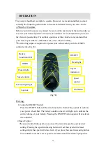
Controller Display 

The controller display is a multifunction visual display. It can provide five 

types of information:1)ON/OFF status ,2)battery condition meter, 3) Horn , 4) 

acceleration, 5)deceleration buttons, 6)tilt function. 

1.


ON/OFF Status 

When the power is on, the controller’s LED will be lit up. If the LED is not 

lit, the controller is OFF. 

2.Battery Condition Meter   

The battery condition meter is composed of 10 segments (three of red, four of 

yellow, and three of green). It enables you to monitor battery charge. The 

battery condition meter indicates the approximate amount of battery charge 

Содержание P16RTL

Страница 1: ...1 USERS MANUAL P16RTL HEARTWAY MEDICAL PRODUCTS CO LTD Part no 70030125...

Страница 2: ...please check whether you have received the following main components as our standard specification See Fig 1 1 Main frame with motor 7 Footrest Left 2 Backrest 8 Controller 3 Seat with Lights 9 Charge...

Страница 3: ...in excessive current draw from the batteries increased tire wear and the rapid wearing of the gearboxes and motors 7 To brake in an emergency simply release the joystick Ramps and Curbs 8 When driving...

Страница 4: ...rning the vehicle off Use While Under The Influence Of Medication Or Alcohol 19 Check with your physician if you are taking any medication that may affect your ability to operate your power wheelchair...

Страница 5: ...er meter V m Each powered wheelchair can resist EMI up to a certain intensity This is called immunity level The higher the immunity level the greater the protection At this time current technology is...

Страница 6: ...cause electronic malfunction or promote premature corrosion of electrical components and frame B Temperature Some of the parts of the power wheelchair are susceptible to change in tempera ture The con...

Страница 7: ...nection point and make sure that tighten the tension knob in the front connection point See Fig 3 Put the seat 3 on the saddle set in the correct direction See Fig 4 Front connection point Fig 3 Fig 4...

Страница 8: ...acket on the seat frame and go through the 2 M8 bolts into the holes of the seat frame See Fig 7 Use the Allen key and wrench to tighten the bolts and nuts See Fig 8 Insert the skirt guard support tub...

Страница 9: ...d will hit the armrest bottom tube if you assemble on the backward hole location Fig 13 2 The right skirt guards is lower than the left one because the controller swingway bracket will lead the right...

Страница 10: ...o the clamp then fasten the lever See Fig17 Fig 17 5 Installing the Footrest Insert the footrest with left 7 and Right 6 each into footrest frame with side direction See Fig 18 then turn 90 degree to...

Страница 11: ...22 You have to plug in the main frame for other cables connect for color by color and make sure tightly See Fig 21 Fig 20 Fig 21 7 Installing the Lights The lights already pre assembly in the saddle...

Страница 12: ...tteries Take out the cover from the base frame slightly Put the batteries to the battery loops and connect the cable 2 ends with the battery positive and negative poles in batteries See Fig 24 Note Th...

Страница 13: ...stment A 1 To adjust the Height wrench Fig 25 Fig 26 Allen key take off the plastic end cap Fig 25 loosen the bolt with Allen key No 6 and Wrench 13 Fig 26 move and locate the bolt into the desired he...

Страница 14: ...olts in footrest frame Fig 29 slide the footrest frame in or out for desired depth tighten the bolts with Allen key B 2 To adjust the Width Bolts Fig 30 use Allen keys to loosen the 4 bolts under the...

Страница 15: ...le loosen the bolt with Allen key No 6 and wrench 13 move the backrest to your comfortable angle See Fig 32 insert the bolt and nut and tighten Note There are 7 different angles when you adjust the ba...

Страница 16: ...ackrest tube loosen the bolts with Allen key No 5 slide in or out for the tube left and right separately to your desired width See Fig 35 tighten the bolts and nuts Fig 34 Fig 35 Allen Key E Controlle...

Страница 17: ...oller See Fig 38 Fig 38 Driving 1 Controller ON OFF Switch Press the ON OFF button I O switch located in front of the joystick to activate your power wheelchair The battery condition meter will light...

Страница 18: ...rp operation of the joystick will result in drastic transitions in direction and velocity When the wheelchair is in operation the surface of the charger will become slightly hot In case of emergency l...

Страница 19: ...e power is OFF they also have a manual feature that allows them to free wheel Free wheeling is accomplished by turning the free wheeling levers to the freewheeling position See Fig 40 Warning Never fr...

Страница 20: ...eed of the power wheelchair The reduction of the speed allows the electrical components to cool down Although your power wheelchair will resume its normal speed when the temperature returns to a safe...

Страница 21: ...ng deep discharge and also are unsafe for use in power chairs The useful life of a battery is quite often a reflection of the care it receives CHARGER The battery charger takes the standard wall outle...

Страница 22: ...replace both batteries at the same time if the batteries are weak If the chair will not be used for a long period of time arrange to have the batteries fully charged for at least once every month Acco...

Страница 23: ...Do not over tighten any screws 3 Check for proper tire inflation Your power wheelchair comes with standard flat free solid tires If your power wheelchair comes with optional air tires make sure to mai...

Страница 24: ...rotecting it from rain or water Never hose off your power wheelchair or place it in direct contact with water 2 Keep wheels free from lint hair sand and carpet fibers 3 Visually inspect the tire tread...

Страница 25: ...ion Check the left motor connection 3 The left motor has a short circuit to a battery connection Contact your local dealer 4 The right motor has a bad connection Check the right motor connection 5 The...

Отзывы: