Place the stove in the intended position and lift out the
hotplate, checking that the joint between the underside of
the hob and the top of the stove is intact. Any joints which
have opened shoud be made good with the fire cement
provided.
Replace the hotplate making sure that it seated evenly on
the soft rope and that it is approximately 0.1” (1.5mm)
higher than the enamelled top plate, with an equal space
all round. Fit the flue chamber which should have a rope
seal already installed. The flue chamber is screwed to the
stove making a good seal as any air leak at this point will
impede the working of the stove.
P/N - RS4M301136 A
Flue Chamber Box is located in Main Oven compartment
during shipment.
Remove all bubble wrap and protective film from inside of
oven doors prior to stove ignition.
Refer to Fig. 10 for definition of terms and installation
orientation of Flue Chamber.
a. Remove two screws (1/4” x 20) and fiber washers from
oven top cutout.
b. Prior to positoning Flue Chamber, ensure that chamber
damper is in its full open position to allow bar for
access to screw hole locations.
c. Position Flue Chamber on stove top ensuring that it is
nested as close as possible to the stove top, to allow
for a minimal gap - front and side.
d. Install fiber washers and 1/4” x 20 screws - ensuring
fasteners are tightly securing Flue Chamber.
e. Close Flue Chamber door.
Open the firebox and ashpit doors and check that the
reciprocating bottom grate bars are in position. Make sure
the three restriction plates are in place on the bottom grate
- one at the front and two at the rear. The riddling lever will
not operate with restriction plates in place, it is intended
for cleaning purposes only.
Be sure to read the sections on clearances, floor
protection and chimneys before actively starting the
installation.
A woodburning stove radiates heat in all directions. Heat
directed towards living areas in front of the stove is usually
very welcome. However, heat radiating in other directions
will not be as welcome if it results in overheating nearby
walls, ceilings or floors.
An important part of planning a safe installation is to be
sure that the combustible material located near your stove
does not overheat.
Clearance is the distance between your stove and
stovepipe and nearby walls, ceiling or floors.
If there is adequate clearance, then the nearby surfaces
will not overheat.
It is very important that you match the stove pipe you are
using to the clearance specified. Failure to do so will result
in an unsafe condition.
Unit must be placed on a continuous non-combustible pad
(floor tile with grouting or sheet metal pad) extending
21”(540mm) in front and 8” (203mm) to the side and back.
Air flowing between the stove pipe and nearby surfaces
carries away heat. Do not fill the empty space with any
insulating material.
A chimney approved to U L C 629 in Canada or UL 103
HT in the USA must be used to connect to the stove
pipe.
Handrail:
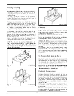
The handrail brackets are held on the front ends of the
stove top-plate casting. Remove the travel nuts and
replace with the handrail brackets ensuring the fibre
protecting washers are in position. Insert the handrail with
fitted endcaps into the brackets, positioning them
correctly, and tighten the locating bolts (See Fig. 1).
Do
not use handrail to move stove.
Endcaps, brackets and hardware, referenced in Fig. 1 are
located in the lower warming drawer during shipment.
Handrail is located on stovetop in a round tube during
shipment.
Do not hang combustible material on handrail during
stove operation.
Clearances must be maintained at all combustible
material. These include doors, trim, furniture, drapes,
newspapers and clothes. See local codes for a
description of combustible material.
Make sure that no floor or chimney supports will be cut
due to chimney installation.
Contact local building officials about restrictions and
installation inspection in your area.
Installation
Fig. 1
DESN 515137
Warning
The ashpit and firebox door must be closed
during normal use, except when lighting or
refuelling
6


