


"Duzy" Gas Log Sets – The Look and Feel of a Real Wood Fire
8
Hearth & Home Technologies • VDY 24/18/30 Gas Log Heater Install/Owner's Manual • 32D1999 • Rev J • 01/22
GAS LINE CONNECTION
The heater gas inlet connection is 3/8" NPT at the reg
-
ulator, inlet on the right side facing the gas log. If a left
side connection is required, the connecting pipe may be
led under the rear of the gas logs or behind the grate for
connection to the inlet.
NOTE:
The millivolt valve has an internal regulator, thus
the incoming gas line connects directly to the valve.
Test all gas joints from the gas meter to the appliance
regulator for leaks using a gas analyzer or soap and water
solution after completing connection.
DO NOT USE AN
OPEN FLAME.
Check the gas pressure with the appliance burning.
MANUAL CONTROL
Figure 6
The pressure regulator is preset and locked to discourage
tampering. If the pressure is not as specified, replace with
the correct part from the parts list in this manual.
Remove 1/8" NPT plug, located on side of regulator body.
Install fitting and tubing to pressure gauge. After taking
pressure reading, re-install test plug. Check for gas leaks.
FP2499
manual valve
NPT Test Plug
FP2499
Figure 6 -
Manual Control Pressure
Test Point Location
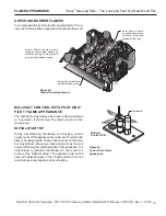
MILLIVOLT CONTROL
Figure 7
The valve regulator controls the burner pressure which
should be checked at the pressure test point. Turn captured
screw counter clockwise 2 or 3 turns and then place tubing
to pressure gauge over test point (Use test point labeled
“OUT”). After taking pressure reading, be sure and turn
captured screw clockwise firmly to re-seal. Do not over
torque. Check for gas leaks.
FP2856
millivolt valve
Test Port "Out"
FP2856
Figure 7 -
Pressure Test Point Location


