Hearth and Home Technologies PVK-80 Скачать руководство пользователя страница 11

11

Heat & Glo  •  PVK-80 Power Vent Instructions •  655-900  Rev. O  •  12/09

(ORANGE)

(GREEN)

GROUND

BLACK

IPI

VALVE

FLAME

SOLENOID

(BLACK)

(WHITE)

(GROUND)

TO HEAT ZONE

FAN

CONNECTION

(BLACK)

(BLACK)

AC

PLUG

FLAME HIGH/LOW

FLAME ON

(RED)

(RED)

(ORANGE)

(ORANGE)

GROUND PIGTAIL

GREEN

JUNCTION BOX

(YELLOW)

(YELLOW)

FACTORY

CONNECTED

TOGETHER

FAN THEMOSTAT

AUX

CONNECTION

(BLACK)

PLUG-ADP

IPI

MODULE

IPI PILOT

3V DC

(BLACK)

(RED)

(BROWN)

(BROWN)

RED

GREEN

YELLOW (H&G)

WHITE (HTL)

REAR VIEW

FRONT VIEW

FIREBOX

BACK

LIGHT 1

BACK

LIGHT 2

R

Y

G

G

Y R

PVK-80 POWERVENT

(BLACK)

(BROWN)

(RED)

(WHITE)

(WHITE)

(BLACK)

(BROWN)

(RED)

(BROWN)

(BROWN)

(RED)

(BLACK)

(GREEN)

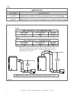
NOTE 1:  BROWN AND RED WIRES FROM 
PVK-80 ARE FOR THE VACUUM SWITCH

NOTE 2:  BLACK, WHITE AND GREEN WIRES 
RUN PVK-80 MOTOR.

NOTE 3:  GREEN WIRE FROM PVK-80 SHOULD 
TIE INTO GROUND A THE JUNCTION BOX 
WHERE 110V SERVICE IS REQUIRED.

Figure 19.  IPI Wiring Diagram For WSK-MLT

Содержание PVK-80

Страница 1: ... at least 2 feet above the finished graded and 2 feet above any combustible projection Note The PVK 80 Power Vent must terminate in a HORIZONTAL position See Figure 1 2 Install vent system components per planned vent run Route the vent pipe from the fireplace to the Power Vent using the minimum number of elbows possible Refer to Tables 2 and 3 for vent specifica tions per size of vent pipe used Note ...

Страница 2: ... 4 3 A vent pipe adaptor must be installed on the fireplace vent collars if a smaller vent pipe than the fireplace starting collars is to be used in the vent system Adaptors are also used to connect the last smaller vent system component to the Power Vent cap SEE TABLE 1 FOR ADAPTOR DESCRIPTIONS 4 After determining the location of the vent system termination point see Step 1 cut a 10 in X 10 in for ...

Страница 3: ...e Fasten the other end of each brace to the outside wall See Figure 4 WIRING THE POWER VENT Note Electrical wiring must be done in accordance with national provincial and or local electric codes Note Some fireplace models may have unique wiring requirements when used with the PVK 80 In those cases PVK 80 instructions those manuals supersede these instructions CAUTION Before performing any maintenan...

Страница 4: ...5 006 Hardware Bag 655 900A 6 Plug one end of the black wire harness into one of the HOT terminals on the junction box Plug the other female end into the back of the rocker switch where the brown wires were removed in Step 6 7 Plug the white wire from the terminal block har ness into one of the NEUTRAL terminals of the junction box 8 Plug the black wire from the terminal block har ness into the ba...

Страница 5: ...tion Inspection If the burner flames are short active and jumping remove the lever screw and slightly close the ex haust control Check the burner flames and adjust the lever again as necessary until the flames are stable strong and steady If the burner flames are tall lifting floating and ghost like the exhaust control is closed too far and MUST be opened When the burner flames have been optimized secur...

Страница 6: ...h the cable loosened from the power vent as sembly remove the sheetmetal screws used to secure the power vent assembly in place Firmly support the assembly to prevent the unit from falling after the sheetmetal screws have been removed See Figure 10 E Remove the sheetmetal screws from the 10 1 2 in diameter pipe and remove the inner ring from inside the collar See Figure 11 IMPORTANT Take special n...

Страница 7: ...wires back through the hole on the collar and tighten the nut on the right angle connector Reconnect the brown and red wire to the vacuum switch and connect the black and white wires to the fan motor CAUTION Make sure the cable is NOT in the path of the hot exhaust air This can cause the wire insulation to melt and the Power Vent to malfunction G Reattach the end cap to the cap assembly with four ...

Страница 8: ...6 90 12 DIRECT VENT WITH 5 in 8 in DIAMETER DVP PIPE MAX ELBOWS 45 90 MAX TOTAL VENT RUN FT MAX VERT DROP FT 10 90 12 ADAPTOR KITS PART NUMBER PART DESCRIPTION SL 2DVP Adapts from 4 in 6 5 8 in SL D series starting collars to 5 in 8 in DVP vent pipe DVP 2SL Adapts from 5 in 8 in DVP series starting collars to 4 in 6 5 8 SL D series vent pipe Table 1 Note Some fireplace models may have unique wiring...

Страница 9: ... TERMINAL BLOCK BLK WHT BRN RED 120 V MOTOR VACUUM SWITCH BLK WHT BRN RED TO REMOTE OR WALL SWITCH This connection is 120 VAC use appropriate wire and switches VALVE GREEN ORANGE WHT ORG GROUND TO FIREPLACE CHASSIS INTERMITTENT PILOT IGNITOR IGNITION MODULE 3 VAC BRN BRN TRANSFORMER 3 VAC PIGGYBACK SWITCH Figure 18 IPI Wiring Diagram With Pvk 80 Installed System 4 Note Remove battery pack from the...

Страница 10: ...h See Detail A This switch must be manually turned ON and OFF whenever the fireplace is operated with the WSK 300 wall panel By turning the Power Vent ON the suction created by the Power Vent closes the vacuum switch which completes the circuit on the cable assembly BRN Wire enabling the ignition sequence of the WSK300 HNG to operate the fireplace A1 A2 A3 HI LOW JUNCTION BOX 110V MINIMUM 14 3 AWG...

Страница 11: ...CONNECTION BLACK PLUG ADP IPI MODULE IPI PILOT 3V DC BLACK RED BROWN BROWN RED GREEN YELLOW H G WHITE HTL REAR VIEW FRONT VIEW FIREBOX BACK LIGHT 1 BACK LIGHT 2 R Y G G Y R PVK 80 POWERVENT BLACK BROWN RED WHITE WHITE BLACK BROWN RED BROWN BROWN RED BLACK GREEN NOTE 1 BROWN AND RED WIRES FROM PVK 80 ARE FOR THE VACUUM SWITCH NOTE 2 BLACK WHITE AND GREEN WIRES RUN PVK 80 MOTOR NOTE 3 GREEN WIRE FRO...

Отзывы: