


10
Heat & Glo • PVK-80 Power Vent Instructions • 655-900 Rev. O • 12/09
ORG
WHT
GROUND
ORG
GRN
RED
YEL/WHT
GRN
RED
BLK
GRN
BLK
ORG
BRN
BRN
NOT
CONNECTED
BATTERY
PACK
IPI MODULE
NOT
USED
INTERMITTENT
PILOT
DEXEN IPI VALVE
CONTROL MODULE
JUNCTION BOX (110V)
WALL SWITCH
BACK VIEW
TO
GROUND
CLIP
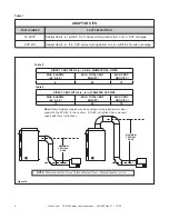
BROWN wire on cable assembly from
WSK300-HNG to module is cut in half. One
end of brown wire connects to one lead from
vacuum switch, the other brown wire connects
to the other lead wire from the vacuum switch.
6000GLX-IPI / Cerona 36 & 42: Power Vent must be
wired to an external 120VAC wall switch (See Detail A).
This switch must be manually turned "ON" and "OFF"
whenever the fireplace is operated with the WSK-300
wall panel.
By turning the Power Vent "ON" the suction created by
the Power Vent closes the vacuum switch which completes
the circuit on the cable assembly (BRN Wire) enabling
the ignition sequence of the WSK300-HNG to operate
the fireplace.
A1 A2 A3 HI/LOW
JUNCTION BOX (110V)
MINIMUM 14-3 AWG
WITH GROUND
RED
RED
BLACK
WHITE
GREEN
RED
BLACK
WHITE
GREEN
BLACK
WHITE
GREEN
RED
POWER
SUPPLY WIRES
SWITCH BOX
SWITCH
Vacuum Switch is located inside the
PVK Termination Cap
Vacuum Switch
PVK Termination Cap
Detail A
See Detail A for J-Box/
Wall Switch Wiring
Detail B
See Detail B
BROWN
PVK-80 plugs into
“FAN” outlet on
junction box.
Figure 18. Wiring Diagram For WSK-300HNG


