Hearth & Home Technologies • B36S-AU Installation Manual • 2563-980 • 10/19
30
A. Pipe Clearances to Combustibles
WARNING! Risk of Fire!
Maintain air space clearance
to vent.
DO NOT
pack insulation or other combustibles:
• Between ceiling firestops
• Between wall shield firestops
• Around vent system
Failure to keep insulation or other material away from
vent pipe could cause overheating and fire.
5
Vent Clearances and Framing
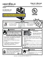
Figure 5.1 Horizontal Venting Clearances To Combustible
Materials - Generic Appliance Shown
* When using SLP pipe, minimum clearances from the vent pipe to combustible materi-
als at inside wall firestops are:
Top: 2-1/2 in. (64 mm)
Bottom: 1/2 in. (13 mm)
Sides: 1 in. (25 mm)
Note: Heat shields MUST overlap by a minimum of 1-1/2 in. (38 mm).
•
DVP heat shield
- designed to be used on a wall 4 in. to 7-1/4 in. (102 mm to 184
mm)
thick
.
• If wall thickness is less than 4 in. (102 mm) the existing heat shields must be field
trimmed. If wall thickness is greater than 7-1/4 in. (184 mm) a DVP-HSM-B will be
required.
•
SLP heat shield
- designed to be used on a wall 4-3/8 in. to 7-5/8 in. (111 mm to
194 mm thick).
• If wall thickness is less than 4-3/8 (111 mm) the existing heat shields must be field
trimmed. If wall thickness is greater than 7-5/8 in. (194 mm) a DVP-HSM-B will be
required.
(DVP-SLP Pipe Shown)
3 in. (76 mm)
top clearance *
1 in. (25 mm)
clearance
bottom & sides
Heat
Shield
Wall
Shield
Firestop
Heat
Shield
WALL
3 in. (76 mm)
top clearance *
1 in. (25 mm)
clearance
bottom & sides
Heat
Shield
Wall
Shield
Firestop
Heat
Shield
WALL
3 in. (76 mm)
top clearance
1 in. (25 mm)
clearance around
vertical sections
SLP Pipe
DVP Pipe
WARNING! Risk of Fire!
Elbow heat shield
MUST
be
installed if required. Overheating will occur.
CORRECT
INCORRECT
COMBUSTIBLE SURFACE
DIRECTION
UP
HEAT SHIELD
90º ELBOW
Figure 5.3
To Install Elbow Heat Shield:
1. Remove the elbow heat shield from the shipping posi-
tion by removing screws.
2. Fasten the shield in place using the four pilot holes.
The shield should be oriented such that the 13 1/8 inch
dimension (longest dimension) is running in the same
direction the elbow is pointing. The shield should be
centered directly above the elbow, and positioned so
that it creates a 1/2 inch airspace between the shield
and the combustible surface. See Figure 5.3.
Figure 5.2 Conditions Requiring Elbow Heat Shield Installation
Elbow Heat Shield
ELBOW HEAT SHIELD
= 6 IN. (152 mm)
OR LESS
COMBUSTIBLE
SURFACE
Top vented appliances: Installation of the elbow heat
shield is required when the clearance to combustible ma-
terial above the first 90 degree vent elbow is six inches or
less. See Figure 5.2.
Note:
A minimum of three inches clearance from the top
of the pipe to any combusible material must always be
maintained.