background image


- 5 - 


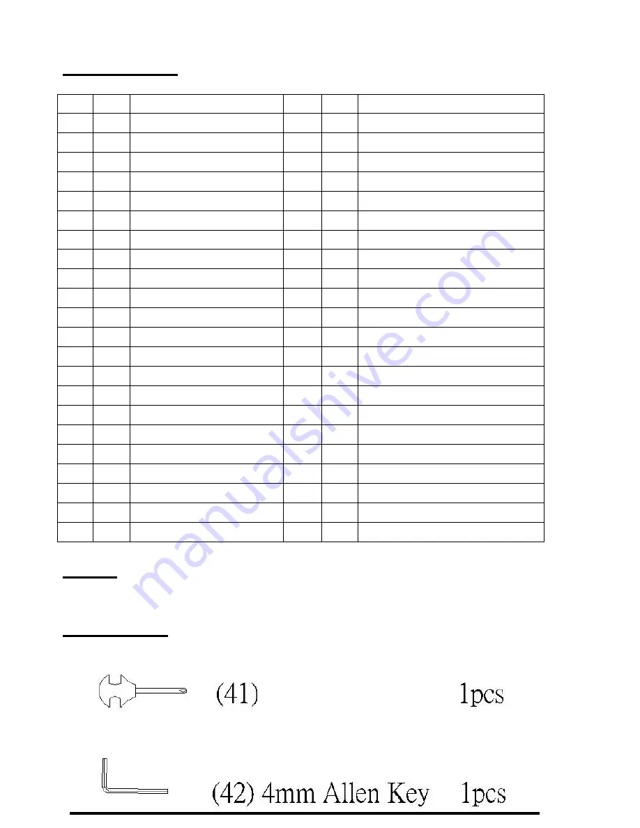
PARTS LIST 


No.  Qty  Description 

NO.  Qty  Description 

Frame 
 

22 

Sensor & Magnet   

Magnetic Flywheel 
 

23 

Plastic Cover 

Flange Nut 3/8*5T 
 

24 

Plastic Cover 

Adjustment Bolt 

25 

Plastic Cover 

Bolt stopper 

26 

Tension Knob 

Idler Support 

27 

Pedal    -LH 

Idler (A) 

28 

Pedal -RH   

Bearing 6000ZZ 

29 

Computer     

Rear Support Tube 

30 

Chain Cover (L) 

10 

Self Drill Screw 
(M6*10) 

31 

Chain Cover (R ) 

11 

Allen Key Bolt 
M8*65 

32 

Acrylic Cover (L/R) 

12 

Locking Nut 3/8*3T 

33 

Plastic Cover 

13 

bowl for crank 

34 

"+" Screw 3/16"*45L 

14 

Steel ball bearing 
rings 

35 

"+" Screw M5*10L 

15 

Steel ball rings-L 

36 

"+" Screw M5*15L 

16 

Steel ball rings-R 

37 

"+" Screw M3*10L 

17 

Washer   

38 

Foot Belt Cover with 
steel-L 

18 

Screw   

39 

Foot Belt Cover with 
steel-R 

19 

Crank 

40 

Washer    D6.6*D16 

20 

Pulley 

41 

Screwdriver 

21 

Belt (6J-340) 

42 

Allen Key 


NOTE 

All of the parts and screws needed for assembly are already in place on the unit.   
 

TOOL SET: 


Screw Driver 

L Tooling 

Содержание PhysioTrainer

Страница 1: ...1 INSTRUCTION MANUAL...

Страница 2: ...mmediately 5 Keep children and pets away from this machine while in use 6 Only one person can use this machine at a time 7 Make sure your machine is correctly assembled before using 8 Do not operate t...

Страница 3: ...journey towards optimum health and fitness We would love to hear from you Please feel free to post a review with the dealer you purchased from or send it to us directly sales hcifitness com Assembly O...

Страница 4: ...4 EXPLODED DRAWING...

Страница 5: ...crew M6 10 31 1 Chain Cover R 11 2 Allen Key Bolt M8 65 32 2 Acrylic Cover L R 12 1 Locking Nut 3 8 3T 33 2 Plastic Cover 13 2 bowl for crank 34 6 Screw 3 16 45L 14 2 Steel ball bearing rings 35 8 Scr...

Страница 6: ...36 Screws Plug the meter cord into the back of the display panel 2 Pedal Assembly Use No 27 for Left side and No 28 for Right side Each pedal crank is marked with either an L or R It is Important to...

Страница 7: ...rned calories during your workout 6 PULSE Requires optional Chest Strap PRESS MODE KEY To select functions of time speed distance calories pulse or scan Hold Mode Key down for 2 seconds to reset the m...

Страница 8: ...pear on display When you start to row the exercise distance will start to count down the computer will beep for 4 seconds after the exercise distance counts down to 0 meter feet c PROGRAMMING MAXIMUM...

Страница 9: ...ght as to be uncomfortable POSITIONING THE TRANSMITTER The transmitter should be positioned below the breast or pectoral muscles with the middle centered on the chest and fasten The transmitter starts...

Отзывы: